
Articulated video probe with magnetic stimulation

a video probe and magnetic stimulation technology, applied in the field of probes, can solve the problem of increasing the number of command transmission errors

Active Publication Date: 2017-11-16
ZAREEI SEYED MOSTAFA +2
View PDF2 Cites 10 Cited by
  • Summary
  • Abstract
  • Description
  • Claims
  • Application Information

AI Technical Summary

Benefits of technology

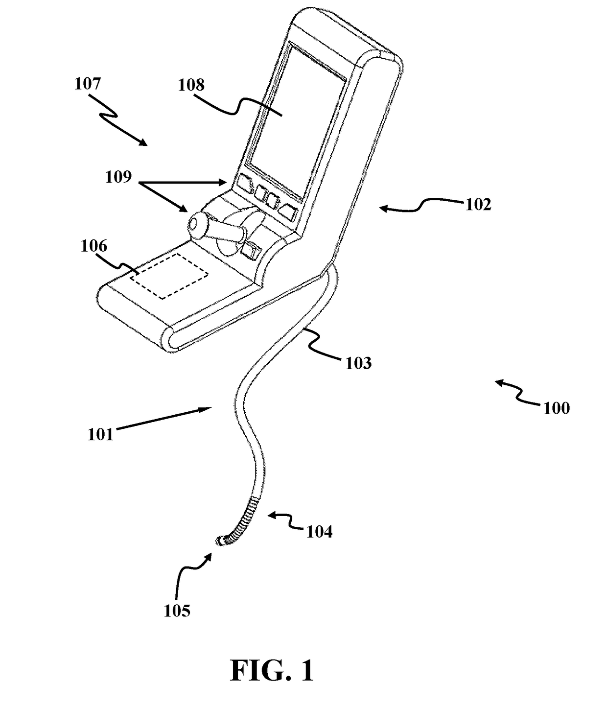
The present patent describes a video probe that includes an articulating portion and a controller that can stimulate the probe to move in different directions. The controller can use electromagnetic coils to attract or repulse other coils on adjoining links, causing the probe to move. The video probe can be used in various applications such as medical procedures or sports equipment. The technical effect of this invention is to provide a flexible and precise tool for visual guidance in various applications.

Problems solved by technology

In addition, in case of long video probes, the odds of command transmission errors become larger.

Method used


Image

  • Articulated video probe with magnetic stimulation
  • Articulated video probe with magnetic stimulation
  • Articulated video probe with magnetic stimulation

Examples


example

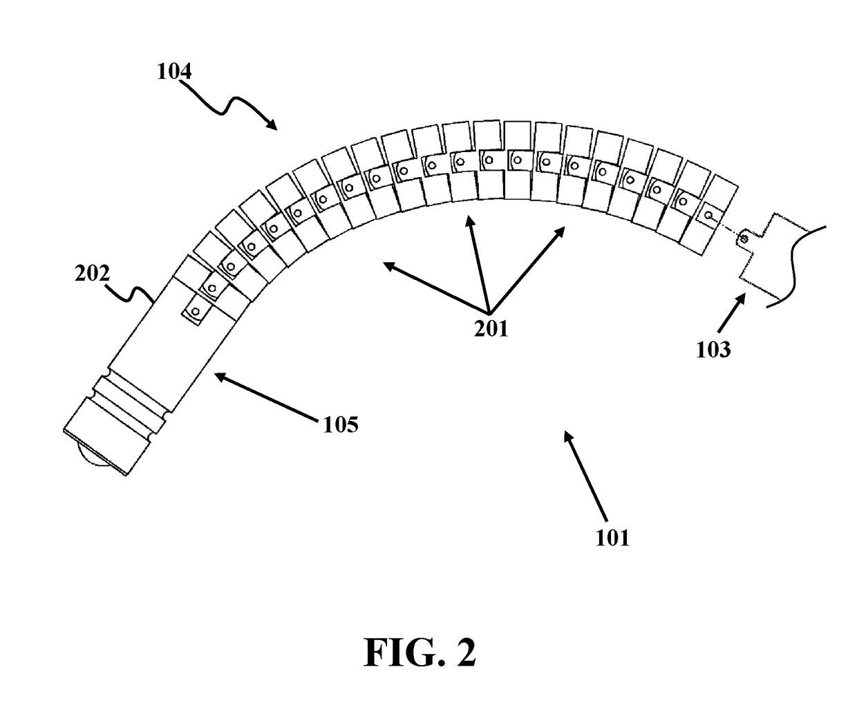
[0046]In this example, an exemplary embodiment of links of an articulating portion of an elongated probe is disclosed. This exemplary embodiment, as described herein may be suitable for video-scopes and borescopes. FIG. 7 illustrates an exemplary embodiment of two adjoining links 701 and 702 in the articulating portion. Link 701 has a diameter 703 of 6 mm, a width 704 of 2 mm, and a thickness 705 of 0.5 mm. All links, including link 702 have similar dimensions as that of link 701. There is a gap 706 of 0.2 mm between links 701 and 702. These dimensions allow for a rotational movement of ±3.8° of each link about its respective rotation axis 707. In this example, the articulating portion has 16 interconnected links, which allows for a ±60° rotation of the articulating portion.


PUM


Abstract

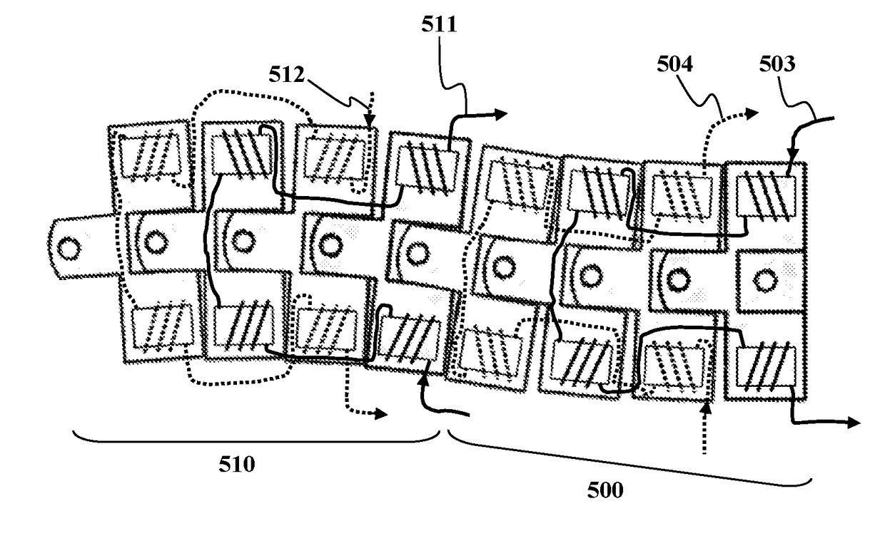
A video probe is disclosed herein that includes an elongated probe including an articulating portion, and a controller functionally coupled with the elongated probe. The articulating portion may include at least two interconnected links and each link may include opposing electromagnetic coils disposed within the link. The controller may be configured to stimulate the opposing electromagnetic coils to attract / repulse corresponding opposing electromagnetic coils of an adjoining link thereby causing the link to pivot about the axis of the single-axis joint.

Description

CROSS REFERENCE TO RELATED APPLICATION[0001]This application claims the benefit of priority from pending U.S. Provisional Patent Application Ser. No. 62 / 377,808, filed on Aug. 22, 2016, and entitled “ARTICULATED VIDEO PROBE MECHANISM WITH MAGNETIC STIMULATION,” which is incorporated herein by reference in its entirety.TECHNICAL FIELD[0002]The present disclosure generally relates to probes for capturing and transmitting images, and particularly to an articulated video probe mechanism with magnetic stimulation.BACKGROUND[0003]A video probe can be used to capture images inside an area of interest. The video probe can include a camera attached to a distal end of an arm, and the arm can be used for navigating the camera inside the area of interest. The arm can be articulated and capable of bending and / or rotating in order to facilitate camera movements within the area of interest, which in most applications is an area with limited access, for example, in medical contexts.[0004]The diamet...

Claims


Application Information

Patent Timeline
IPC IPC(8): H01F7/06B25J18/06H04N5/225
CPCH01F7/064B25J18/06H04N5/2253B25J9/06B25J9/12B25J13/065A61B1/00158A61B1/0055A61B1/0057A61B1/008H04N23/555H04N23/54
Inventor ZAREEI, SEYED MOSTAFABAREKATAIN FARD, MAHDIKALBASI ASHTARI, MOHAMMAD HOSSEIN
Owner ZAREEI SEYED MOSTAFA
Learn More