Vacuum exhaust method

Active Publication Date: 2017-11-30
TOKYO ELECTRON LTD
View PDF2 Cites 2 Cited by
  • Summary
  • Abstract
  • Description
  • Claims
  • Application Information

AI Technical Summary

Benefits of technology

[0006]In view of the above, the disclosure provides a vacuum exhaust method capable

Problems solved by technology

In such a substrate processing apparatus, a desired vacuum level may not be obtained even if a pressure in the processing chamber is decreased by the vacuum pump due to a decrease in evacuation performance of the vacuum pump, the effect of impurities adsorbed onto an inner surface of the processing chamber, or t

Method used


Image

  • Vacuum exhaust method
  • Vacuum exhaust method
  • Vacuum exhaust method

Examples


Embodiment Construction

[0013]Hereinafter, embodiments will be described with reference to the accompanying drawings. Like reference numerals will be used for like parts having substantially the same functions throughout the specification and the drawings, and redundant description thereof will be omitted.

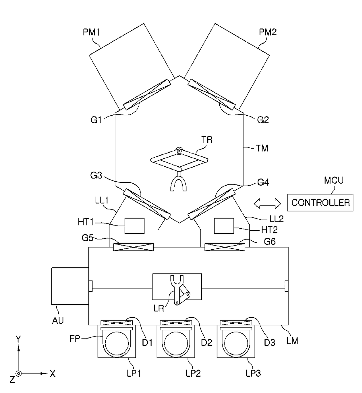
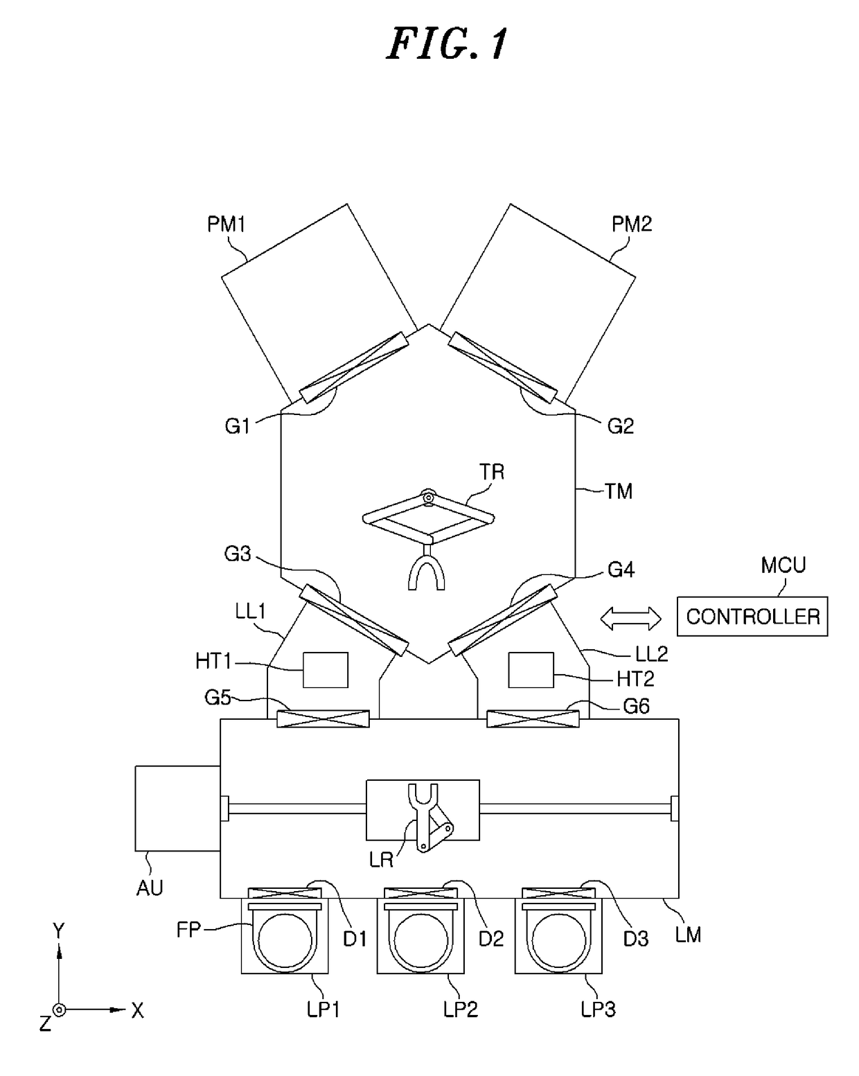
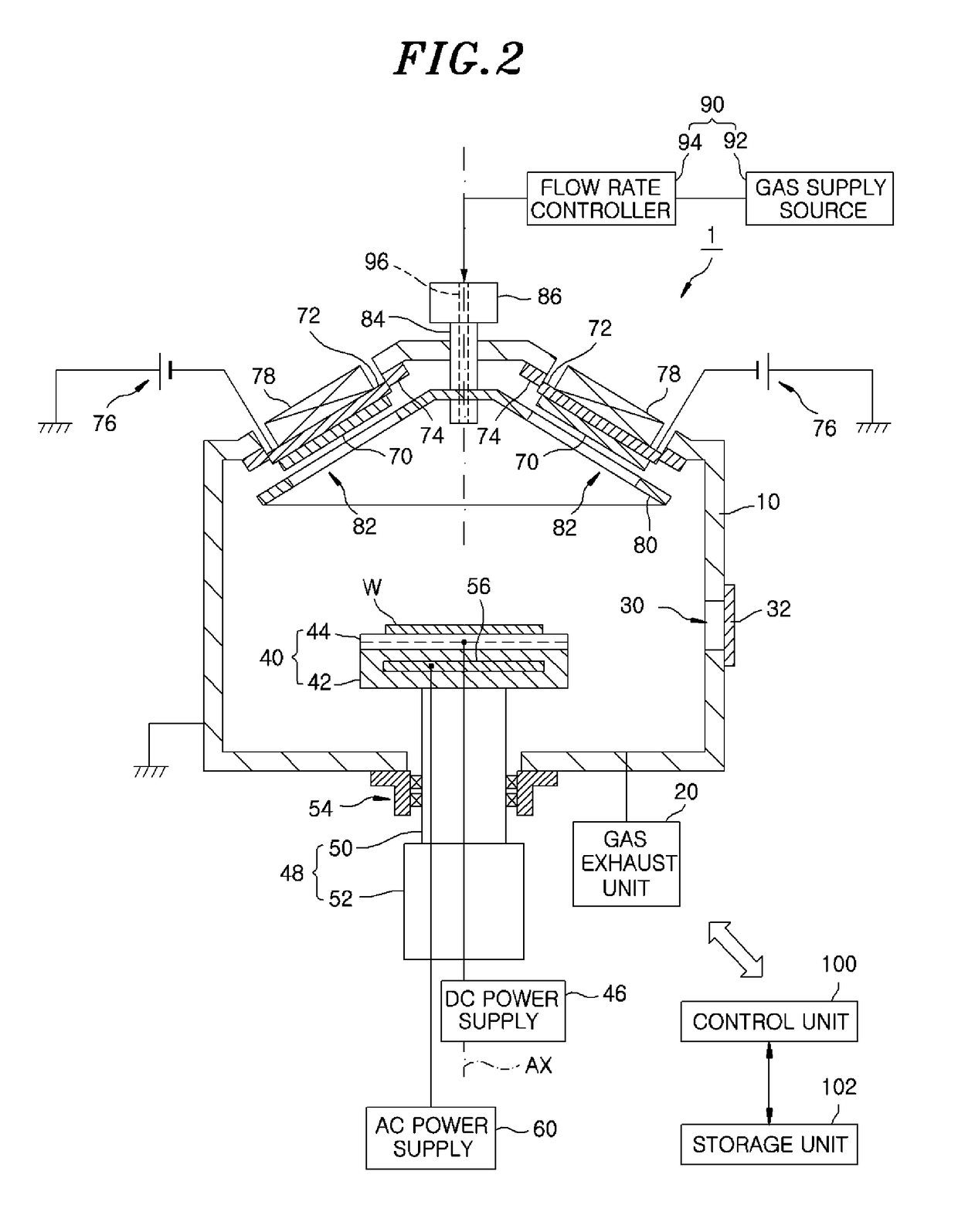
[0014]A vacuum exhaust method according to an embodiment improves a vacuum level in a processing chamber by loading a non-evaporated getter into a processing chamber that can be evacuated by a gas exhaust unit and adsorbing an active gas in the processing chamber onto the non-evaporated getter. The vacuum exhaust method according to an embodiment can be applied to a substrate processing apparatus for performing processing, e.g., film formation, etching, or the like, on a substrate. The vacuum exhaust method according to an embodiment can also be applied to a transfer chamber for transferring a substrate or the like. In this specification, the non-evaporated getter is also referred to as “NEG”.

[0015]In the...


PUM


Abstract

A vacuum exhaust method is for decreasing a pressure in a processing chamber in which a mounting table configured to mount thereon a substrate is provided by using a gas exhaust unit. The vacuum exhaust method includes mounting a non-evaporated getter (NEG) on the mounting table, and adsorbing an active gas in the processing chamber on the NEG mounted on the mounting table. In the adsorbing the active gas, the NEG is maintained at a predetermined temperature.

Description

CROSS-REFERENCE TO RELATED APPLICATION[0001]This application claims priority to Japanese Patent Application No. 2016-103607 filed on May 24, 2016, the entire contents of which are incorporated herein by reference.FIELD OF THE INVENTION[0002]The disclosure relates to a vacuum exhaust method.BACKGROUND OF THE INVENTION[0003]There is known a substrate processing apparatus for performing processing on a substrate loaded into a processing chamber that can be evacuated by a vacuum pump such as a cryo pump or the like. In such a substrate processing apparatus, a desired vacuum level may not be obtained even if a pressure in the processing chamber is decreased by the vacuum pump due to a decrease in evacuation performance of the vacuum pump, the effect of impurities adsorbed onto an inner surface of the processing chamber, or the like.[0004]Therefore, there is conventionally known, as a method of improving a vacuum level in a processing chamber, a method of providing a cooling panel and a g...

Claims


Application Information

Patent Timeline
IPC IPC(8): H01J11/52H01J21/18H01J41/16H01J11/46H01J11/20H01J21/02H01J41/12
CPCH01J11/52H01J41/16H01J21/18H01J11/20H01J41/12H01J21/02H01J11/46H01J7/186H01J37/32724H01J37/32816H01J37/32834
Inventor SAITO, TOMOHIROMITSUNAGA, TADASHIMAEDA, KOUJIMIYASHITA, TETSUYA
Owner TOKYO ELECTRON LTD
Why Eureka
Try Eureka