Actuator body, method for driving actuator, and gripping hand using the same

a technology of actuators and grips, applied in the direction of manipulators, gripping heads, program-controlled manipulators, etc., can solve the problems of undesirable inhibiting of freely moving in a bending direction during the application of pressure to the inside of the rubber tube, and the actuator that makes a flexion action is also undesirable inhibited

Active Publication Date: 2018-01-18
PANASONIC INTELLECTUAL PROPERTY MANAGEMENT CO LTD
View PDF0 Cites 7 Cited by
  • Summary
  • Abstract
  • Description
  • Claims
  • Application Information

AI Technical Summary

Benefits of technology

[0008]The actuator body according to the present disclosure allows an actuator to ma

Problems solved by technology

However, a McKibben-type actuator, which is stretched or contracted in an axial direction by increasing or decreasing fluid pressure therein, is undesirably inhibited from freely moving in a bending direction during application

Method used


Image

  • Actuator body, method for driving actuator, and gripping hand using the same
  • Actuator body, method for driving actuator, and gripping hand using the same
  • Actuator body, method for driving actuator, and gripping hand using the same

Examples


embodiment 1

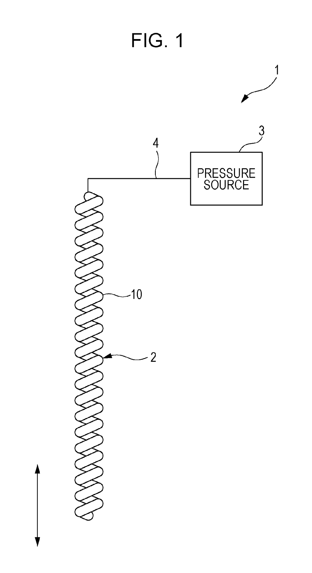
[0086]First, an overall configuration of an actuator 1 is described with reference to FIG. 1. The actuator 1 converts pressure of fluid into a change of a degree of flexion and includes an actuator body 2, a pressure source 3, and a pipe 4.

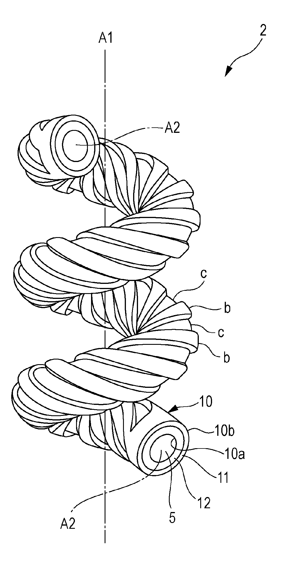
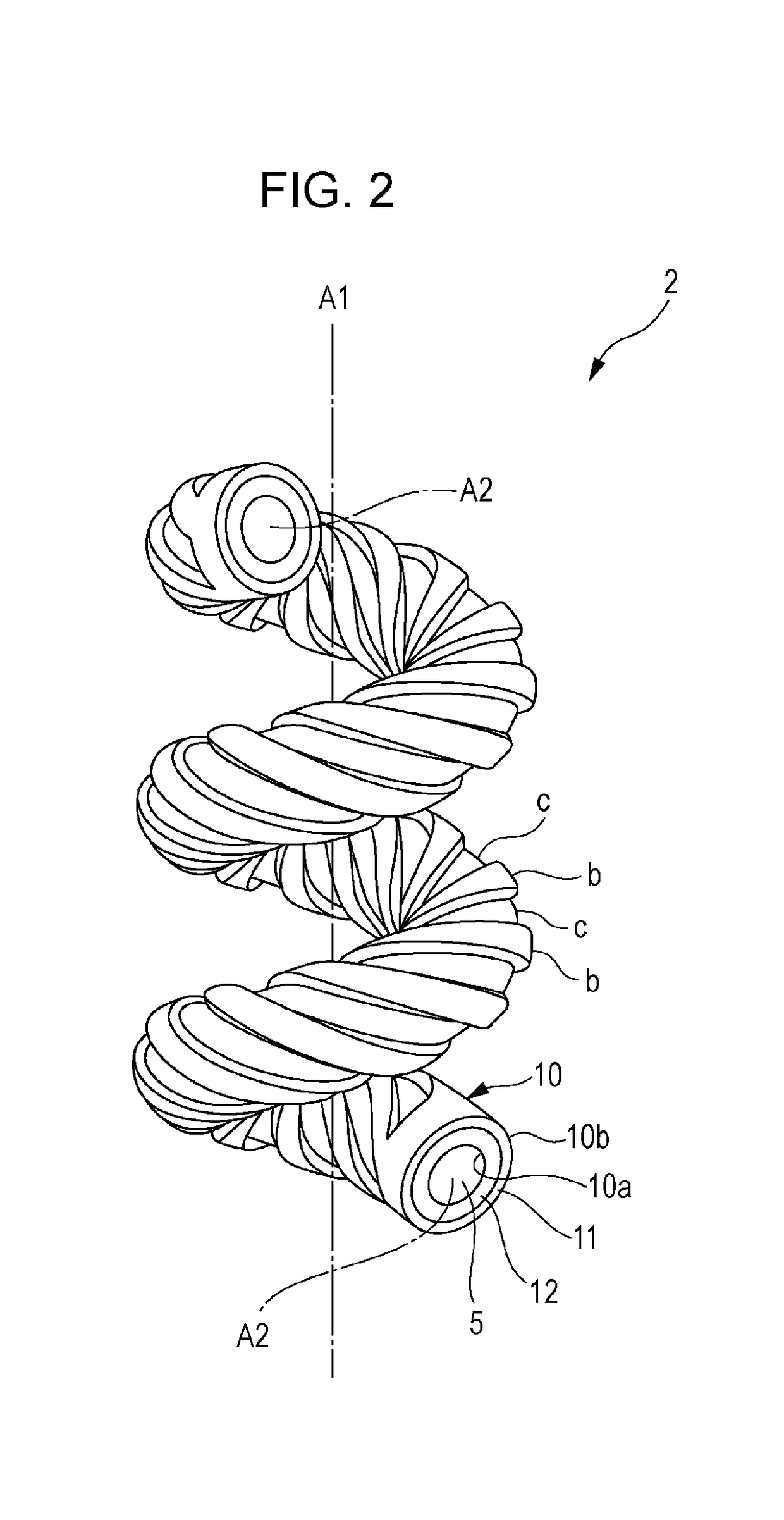
[0087]The actuator body 2 is shaped so that a hollow tube 10 is wound spirally. The tube 10 is filled with fluid such as water. An upper part of the actuator body 2 is fixed to a fixing tool (not illustrated), and an upper end of the actuator body 2 is connected to the pipe 4. A lower end of the actuator body 2 is sealed, for example, by caulking. A configuration of the actuator body 2 will be described in detail later.

[0088]The pressure source 3 brings fluid into and out of the actuator body 2 through the pipe 4 and thereby increases and decreases pressure in the tube 10 of the actuator body 2 and stretches and contracts the actuator body 2.

[0089]As the pressure source 3, for example, a syringe pump (reciprocating pump) is used. The syringe pump ...

embodiment 2

[0144]An actuator body according to Embodiment 2 is different from that according to Embodiment 1 in that a first elastic member 11 and a second elastic member 12 are integrated with each other.

[0145]FIG. 15 illustrates part of a tube 10 of an actuator body 2A, and FIG. 16 is a transverse cross-sectional view of the tube 10 of the actuator body 2A. In the following drawings, elements that are similar to those in Embodiment 1 are given similar reference signs, and description thereof is omitted.

[0146]The actuator body 2A is shaped so that the hollow tube 10 having elasticity is wound spirally. The tube 10 is wound about an axis A1 of the actuator body 2A. In an outer circumferential surface 10b of the tube 10, grooves c are provided spirally about an axial center A2 of the tube 10.

[0147]The grooves c of the tube 10 are multiple grooves, and a width thereof is constant. A depth of each of the grooves c is equal to or larger than a half of the thickness of the tube 10. That is, a porti...

embodiment 3

[0153]An actuator body according to Embodiment 3 is different from that according to Embodiment 1 in that a single groove c is provided.

[0154]FIG. 19 illustrates part of a tube 10 of an actuator body 2B according to Embodiment 3.

[0155]The actuator body 2B is also shaped so that the hollow tube 10 having elasticity is wound spirally. The tube 10 is wound about an axis A1 of the actuator body 2B. In an outer circumferential surface 10b of the tube 10, a single groove c is provided spirally about an axial center A2 of the tube 10.

[0156]Specifically, the tube 10 includes a cylindrical first elastic member 11 and a cylindrical second elastic member 12 that is more flexible than the first elastic member 11. The first elastic member 11 has a single through-hole 11c that passes through an inner circumferential surface 11a and an outer circumferential surface 11b. The second elastic member 12 is disposed in contact with an inner side of the first elastic member 11 and blocks the through-hole...


PUM


Abstract

An actuator body includes a tube that has a space therein and is wound spirally about a first axis. The tube has a plurality of first portions and a plurality of second portions, the tube has one or more grooves in at least one of an outer circumferential surface and an inner circumferential surface thereof, and the one or more grooves are provided spirally about a longitudinal axis of the tube, the space is in contact with the inner circumferential surface, and the outer circumferential surface is a surface opposite to the inner circumferential surface, each of the plurality of first portions has higher torsional rigidity than each of the plurality of second portions, the plurality of first portions are aligned along the first axis, and the plurality of first portions do not overlap the plurality of second portions.

Description

BACKGROUND1. Technical Field[0001]The present disclosure relates to an actuator body used in an actuator that converts pressure of fluid into a change in degree of flexion, a method for driving the actuator, and a gripping hand using the actuator.2. Description of the Related Art[0002]Along with increasing demands for a machine, such as a household robot, that works close to humans, there are increasing expectations for an artificial muscle actuator having light-weight and flexible characteristics like human muscles. Although there are various kinds of artificial muscle actuators, most of them are actuators that utilize deformation of a rubber-like elastic material that is compatible with the light-weight and flexible characteristics.[0003]As one of the actuators that utilize deformation of a rubber-like elastic material, a McKibben-type actuator that stretches and contracts due to pressure of fluid is known (see, for example, Japanese Unexamined Patent Application Publication No. 5...

Claims


Application Information

Patent Timeline
IPC IPC(8): F15B15/10B25J15/12
CPCB25J15/12F15B15/10F15B15/103B25J9/142B25J15/0023
Inventor ASAI, KATSUHIKOOZAWA, JUNNAGATA, TAKAYUKIINOUE, KAZUO
Owner PANASONIC INTELLECTUAL PROPERTY MANAGEMENT CO LTD
Why Eureka
Try Eureka