Injection moulding device for producing parts made of plastic

a technology of injection molding and plastic parts, which is applied in the field of multi-layer preforms, can solve the problems of not being able to easily move along with the central part, and achieve the effect of simple and efficient design

Active Publication Date: 2018-01-25
FOBOHA GERMANY
View PDF5 Cites 3 Cited by
  • Summary
  • Abstract
  • Description
  • Claims
  • Application Information

AI Technical Summary

Benefits of technology

[0007]A problem addressed by the invention is that of demonstrating a device for producing plastic parts which has a simpler and more efficient design compared to the prior art. This problem is addressed by the invention as defined in the claims.
[0008]In one embodiment, the invention comprises an injection molding device for producing plastic parts made of one or more material components. The injection molding device has an injection mold with a central part which is able to rotate about a first axis of rotation, arranged between a first and a second mold half and displaceable relative thereto in a first direction. The central part has at least one pair of lateral surfaces, which are opposite one another with respect to the first axis of rotation, said pair forming, in a closed position, cavities together with the first and the second mold halves. A retaining device is used to hold the central part with respect to the first and second mold halves. Furthermore, a transfer device is included, which is arranged laterally adjacent to the central part, at least when in an open position, and which serves to accept plastic parts adhering to a lateral surface of the central part facing the same in this position. The transfer device is advantageously attached to the retaining device of the central part. As a rule, it has a base which can be displaced with respect to the retaining device, as well as a storage means which is able to rotate about a second axis relative to the base. The first and second axes of rotation are advantageously arranged parallel to each other. Depending on the embodiment, however, they can also be arranged at a right angle to one another. In the closed position, liquid plastic is injected into the cavities of the injection molding device in multiple steps / layers to produce the parts. For example, sub-regions of the plastic parts to be produced are produced in the cavities between the central part and the first mold half. Subsequently, the injection mold is opened by the relative displacement of the first and second mold halves with respect to the central part, and the central part is then rotated with the sub-regions adhering thereto around the first axis of rotation until the sub-regions are arranged between the central part and the second mold half. Subsequently, the injection mold is closed again and the same, or a second, material component is injected onto the first sub-region. Next, the injection mold is opened again and the central part is rotated by a further 90° so that the parts come to lie opposite the transfer device, which takes them off.

Problems solved by technology

A disadvantage is that these cannot be easily moved along with the central part.

Method used


Image

  • Injection moulding device for producing parts made of plastic
  • Injection moulding device for producing parts made of plastic
  • Injection moulding device for producing parts made of plastic

Examples


Embodiment Construction

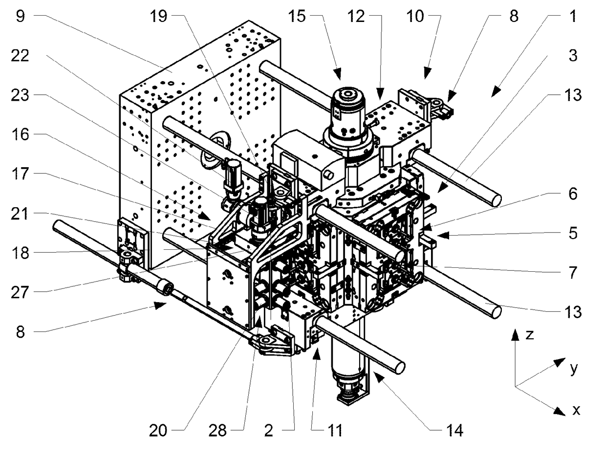
[0016]FIG. 1 shows an embodiment of a device 1 for the production of plastic parts 2 (see FIG. 5) made of one or more material components. The plastic parts 2 to be produced can, for example, be constructed of one or more layers. In the embodiment shown, the device 1 is used for the production of preforms 2 for the manufacture of PET bottles by blow molding.

[0017]The device 1 has an injection mold 3, which is only partially shown here. The injection mold 3 has a central part 5, which is able to rotate about a first axis of rotation 4, which is arranged between a first and a second half of the mold (not shown in detail), and which has at least one pair of lateral surfaces 6 opposite one another with respect to the first axis of rotation 4 of the central part 5. In the embodiment shown, the central part 5 has four lateral surfaces 6, wherein each pair of opposing lateral surfaces 6 are associated with each other. In a closed position (not shown), the lateral surfaces 6, together with ...


PUM

PropertyMeasurementUnit
circumferenceaaaaaaaaaa
dimensional stabilityaaaaaaaaaa
rotationaaaaaaaaaa

Abstract

The invention relates to an injection molding device (1) for producing plastic parts (2) consisting of one or more material components. The injection molding device (1) comprises an injection mold (3) having a center part (5) that is rotatable about a first axis of rotation (4), which center part is arranged between a first and a second mold half and which can be moved relative to said mold halves in a first direction. The center part (5) has cavities (7) on the lateral surfaces (6). A retaining device (10) is used to retain the center part (5) in the injection molding device (1). A transfer device (16) is arranged laterally next to the center part (5) at least in an open position and is used to transfer plastic parts (2) into a storage means (2).

Description

BACKGROUND OF THE INVENTIONField of the Invention[0001]The invention relates to a device for the production of parts made of a plurality of plastic components, in particular multilayer preforms, as well as a handling device for the same.Discussion of Related Art[0002]Injection molding devices for the production of single and multi-layer preforms, as well as cooling devices for cooling the same, are known from the prior art. Because the preforms are thick-walled and therefore require a comparatively long time until they are sufficiently cooled, on the one hand, and because, on the other hand, high dimensional stability is required in certain areas, special cooling and handling devices are used to cool the preforms from an injection molding device.[0003]U.S. Pat. No. 4,836,767 was published in 1989 of behalf of the Husky corporation. US'767 relates to a device which is used for the simultaneous production and cooling of plastic parts. A carrier plate, which is part of the injection mo...

Claims


Application Information

Patent Timeline
Patent Type & Authority Applications(United States)
IPC IPC(8): B29C45/16B29C45/76B29C45/42
CPCB29K2105/253B29C2045/1626B29C2045/7228B29C45/4225B29C45/1628B29C45/1618B29C45/7686
Inventor ARMBRUSTER, RAINER
Owner FOBOHA GERMANY
Why Eureka
Try Eureka