Apparatus and method for reducing precision of data

a data and approximation technology, applied in the field of approximation and data precision reduction, can solve the problems of reducing the accuracy of fixed point operations, reducing the accuracy of quantizing small numbers, and impractical floating point operations for high-speed applications, so as to reduce the precision of input signals, and reduce the error of rounding.

Inactive Publication Date: 2005-08-04
AVAGO TECH WIRELESS IP SINGAPORE PTE
View PDF32 Cites 5 Cited by
  • Summary
  • Abstract
  • Description
  • Claims
  • Application Information

AI Technical Summary

Benefits of technology

[0003] By contrast, fixed point computations often are used when such as in digital signal processing, extremely high processing rates are desirable. Typically, the word size used to represent a fixed point value is compact relative to floating point, and fixed point computational devices tend to be of simpler, efficient designs, which permit high-speed operation. Most DSP algorithms achieve satisfactory performance in VLSI using fixed-point arithmetic. Therefore, fixed point computations, particularly in the two's complement binary format, are predominant in DSP applications. However, because fixed point systems can only represent a fixed range of numbers, the internal data precision is reduced. In addition to the increased possibility of overflow during a calculation, fixed point operations tend to have a reduce ability to accurately quantize small numbers. Also, fixed point operations tend to require additional digits to represent the precision of the results of an operation. For example, a fixed point multiplication of two signal values, each having an initial precision of m bits, results in a product having 2m bits. Because the word length of a subsequent operation, or data path, may be limited to only m bits, some form of precision reduction is needed.
[0008] What is needed, then, are methods and apparatus that substantially eliminate or offset the precision reduction error. SUMMARY OF THE INVENTION
[0009] The present invention satisfies the above needs by providing methods and apparatus for reducing precision of an input signal having a precision portion and a loss portion, by comparing the loss portion to a preselected threshold value, ft; determining a selectable bias, α, responsive to the comparison of the loss portion, to the preselected threshold value, ft; and combining the precision portion with α, thus creating a reduced precision datum. Selectable bias α corresponds to a predetermined characteristic of one of α, the input datum, the reduced precision datum, and a combination thereof. In preferred embodiments of the invention, selectable bias α is generated such that the Expected Value of selectable bias α is substantially equal to the Expected Value of the error signal between the input data with higher precision and an output signal with lesser precision. In this manner, errors due to rounding are minimized or eliminated.

Problems solved by technology

However, floating point operations can be impractical for high-speed applications, including digital signal processing (DSP), due to the added hardware, overhead, and processing time they demand.
However, because fixed point systems can only represent a fixed range of numbers, the internal data precision is reduced.
In addition to the increased possibility of overflow during a calculation, fixed point operations tend to have a reduce ability to accurately quantize small numbers.
For many DSP systems, performance metrics such as signal-to-noise ratio (SNR) and stability are adversely affected by decreasing internal data precision.
Signal processing typically involves numerous, sequential, iterative and recursive computations, during which uncompensated precision reduction errors accumulate, thereby degrading filter performance, possibly to the point of filter instability.
In some instances, precision reduction errors are merely nuisances with little practical impact.
However, in the extreme, precision reduction errors can lead to disastrous outcomes, such as in the documented failure of a defensive missile battery during the 1991 Persian Gulf War, which resulted in many lost lives.
Because DSP applications are pervasive in modern life, including for example, communications, health care, transportation, defense, and the like, degraded system performance arising from uncompensated precision reduction errors can be of great import.

Method used


Image

  • Apparatus and method for reducing precision of data
  • Apparatus and method for reducing precision of data
  • Apparatus and method for reducing precision of data

Examples


Embodiment Construction

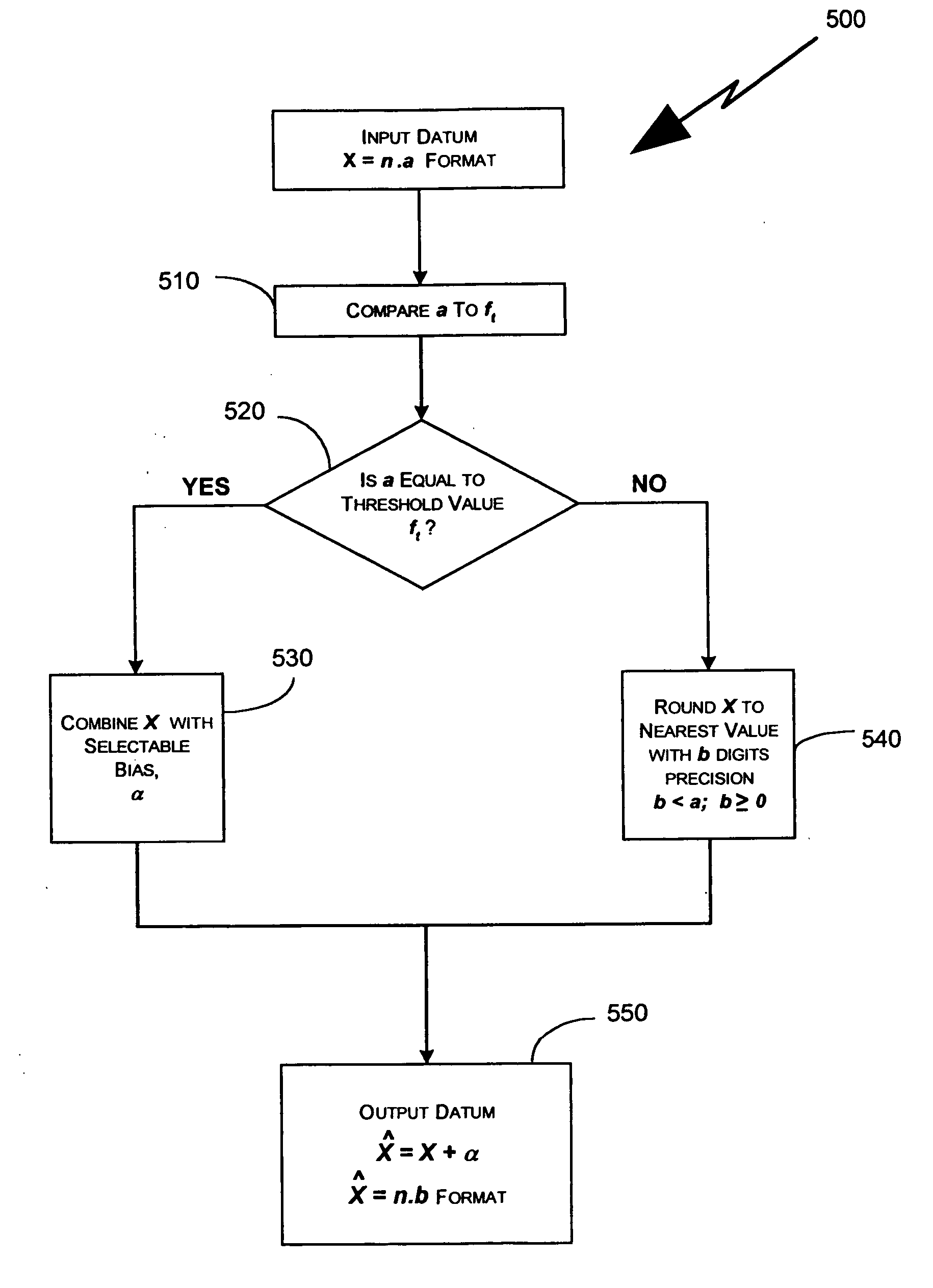
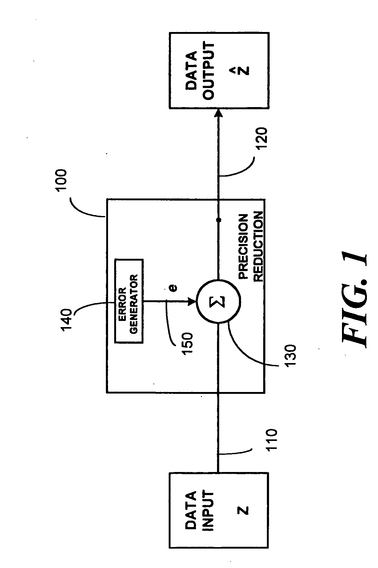
[0029] The present invention includes methods and apparatus that reduce the precision of an input signal value having a first precision to an output signal having a second, lesser precision in a manner that greatly reduces, or substantially cancels, a precision reduction error signal typically inherent in prior art rounding techniques. By combining the input signal with a selectable bias, responsive to a preselected threshold rounding state, the rounding methods and apparatus according to the present invention provide an output signal that is substantially free of precision reduction error bias. In addition, where it is desired to produce a preselected signal offset, values for the selectable bias can be assigned to generate the offset. Such a signal offset may be useful to compensate for a undesirable pre-existing input signal bias, including correcting for precision reduction error biases injected during previous precision reduction operations. Also, it may be useful to impart an ...


PUM


Abstract

Methods and apparatus for reducing precision of an input signal, by comparing a portion of the input signal to a preselected threshold value, and determining a selectable bias responsive to the comparison. By combining a portion of the input signal with the selectable bias, a reduced precision signal, having minimized or eliminated rounding error, is generated. The selectable bias corresponds to a predetermined characteristic of one of bias, an error signal, the input datum, the reduced precision datum, and a combination thereof.

Description

CROSS-REFERENCE TO RELATED APPLICATION(S) [0001] The present application is a continuation of U.S. patent application Ser. No. 09 / 735,170, filed on Dec. 11, 2000, which in turn claims the benefit of U.S. Provisional Patent Application Ser. No. 60 / 170,156, filed on Dec. 10, 1999, the contents of both of which are hereby incorporated by reference.[0002] The implementation of DSP algorithms in VLSI requires trade-offs between factors such as algorithm performance, silicon area, power consumption, and clock frequency. One parameter that affects all of these factors is the word length, or number of bits, used to represent the data. Where extremely precise computations are required, floating point arithmetic may be needed. However, floating point operations can be impractical for high-speed applications, including digital signal processing (DSP), due to the added hardware, overhead, and processing time they demand. [0003] By contrast, fixed point computations often are used when such as i...

Claims


Application Information

Patent Timeline
Patent Type & Authority Applications(United States)
IPC IPC(8): G06F7/00G06F7/38G06F7/48G06F7/499
CPCG06F7/48G06F7/49963G06F7/49942
Inventor DENK, TRACY C.PUTNAM, JEFFREY S.
Owner AVAGO TECH WIRELESS IP SINGAPORE PTE
Why Eureka
Try Eureka