
Steering column for a motor vehicle

a technology for steering columns and motor vehicles, applied in steering parts, vehicle components, transportation and packaging, etc., can solve the problems of difficult control of energy absorption, unsuitability in practice, and restriction of the design of the clamping devi

Active Publication Date: 2018-02-08
THYSSENKRUPP PRESTA AG +1
View PDF1 Cites 6 Cited by
  • Summary
  • Abstract
  • Description
  • Claims
  • Application Information

AI Technical Summary

Benefits of technology

The invention provides a special lifting mechanism for the crash activation of a locking device. This allows for independent movement of the locking part, even when the clamping movement is being done. This results in an optimized movement sequence. The clamping mechanism can have a small clamping stroke with a large clamping force. This ensures secure and firm joining of deep-shaped form-fitting elements on the locking and engagement parts during the crash activation, and during the releasing of the locking device they can be easily moved apart so the form-fitting elements are disengaged and the adjustment unit in the supporting unit can be moved. The engagement part and / or the locking part are / is formed as a sintered part, which makes them simple and economical to produce.

Problems solved by technology

However, it is a drawback of the prior art that the clamping stroke of the clamping device must be at least large enough so that a secure engaging and separating of the form-fitting elements of locking part and engagement part occurs during the locking and releasing, even though the clamping of the adjustment unit requires a smaller clamping stroke or even no clamping stroke, but only a clamping force.
This restricts the design of the clamping device in terms of the clamping stroke and force transmission during the manual locking of the clamping device, when the functionality of the crash device needs to be assured.
The drawback here, however, is that the serration actually provided for the locking may produce an abrupt and hard to control energy absorption, which is therefore unsuitable in practice.

Method used


Image

  • Steering column for a motor vehicle
  • Steering column for a motor vehicle
  • Steering column for a motor vehicle

Examples


Embodiment Construction

[0044]In the various figures, the same parts are always provided with the same reference numbers and therefore as a rule are also only designated or mentioned once.

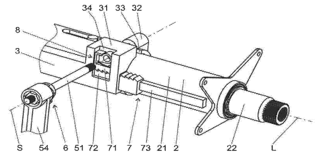
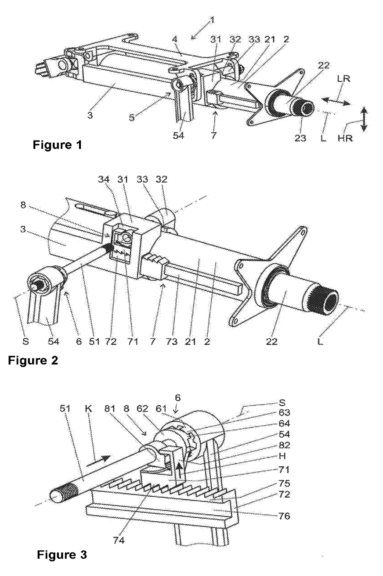
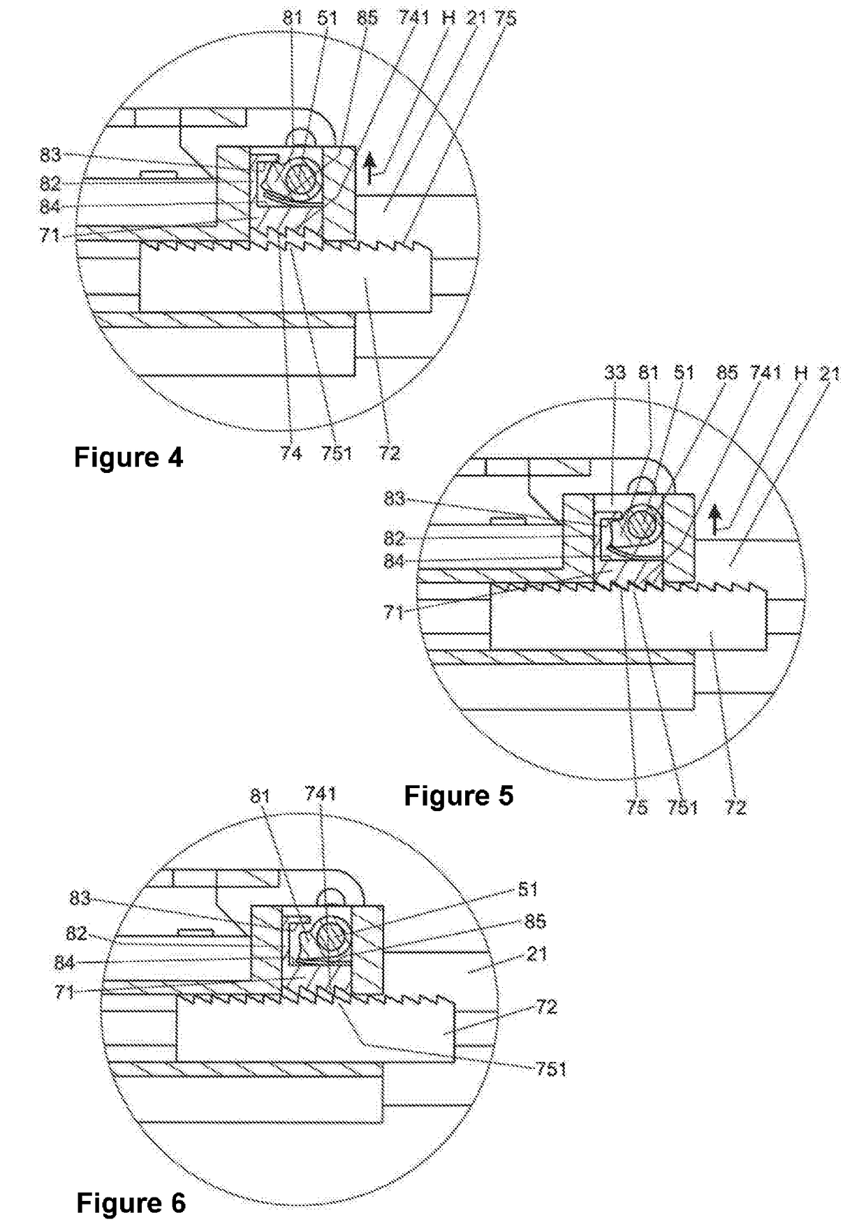
[0045]FIGS. 1 to 3 show a steering column 1, comprising an adjustment unit 2, with a casing tube 21, in which a steering spindle 22 is mounted to be rotatable about the longitudinal axis L. At a rear section 23 of the steering spindle 22 in regard to the driving direction, a steering wheel (not shown) can be attached.

[0046]The adjustment unit 2 is held in a supporting unit 3, which in turn is fastened to a bracket unit 4, which can be arranged on a body of a motor vehicle, not shown.

[0047]The supporting unit 3 comprises a recess in which the adjustment unit 2 is received, while the supporting unit 3 comprises side sections 31 and 32, between which a slot 33 extends in the direction of the longitudinal axis L and on which a clamping force can be exerted by a clamping device 5 transversely to the longitudinal axis L, by whi...


PUM


Abstract

A steering column may include an adjustment unit with a steering spindle that is mounted rotatably about its longitudinal axis in a casing tube, a supporting unit that supports the adjustment unit, and a clamping device that controls movement between the adjustment unit and the supporting unit in a longitudinal direction. The clamping device may comprise an actuating element that interacts with a clamping mechanism for clamping the supporting unit to the adjustment unit. The clamping device may further comprise a locking part. In the securing position a form-fitting element of the locking part engages non-displaceably in the longitudinal direction with a form-fitting element of an engagement part connected to the adjustment unit. In the release position the form-fitting element of the locking part may be spaced apart from the form-fitting element of the engagement part to release the adjustment unit. The actuating element may be connected to a lifting mechanism separate from the clamping mechanism. The lifting mechanism may be connected to the locking part and may convert actuation of the actuating element into a working stroke of the locking part. The working stroke of the lifting mechanism is assignable independently of a clamping stroke of the clamping mechanism.

Description

PRIOR ART[0001]The invention concerns a steering column for a motor vehicle, comprising an adjustment unit with a steering spindle which is mounted rotatably about its longitudinal axis in a casing tube, a supporting unit which is connectable to the body of the motor vehicle and in which the adjustment unit can be accommodated, and a clamping device, which in a securing position secures the adjustment unit relative to the supporting unit in normal operation and which releases a movement of the adjustment unit relative to the supporting unit in at least the longitudinal direction, wherein the clamping device comprises an actuating element, which interacts with a clamping mechanism which converts an actuation of the actuating element into a clamping stroke which is directed transversely to the longitudinal axis for clamping the supporting unit to the adjustment unit, and wherein the clamping device comprises at least one locking part, which is supported in the longitudinal direction o...

Claims


Application Information

Patent Timeline
IPC IPC(8): B62D1/184B62D1/19B62D1/187
CPCB62D1/184B62D1/187B62D1/192B62D1/195
Inventor KREUTZ, DANIELFORTE, SEBASTIANSCHNITZER, HIERONYMUS
Owner THYSSENKRUPP PRESTA AG
Learn More