
Welding fixture

A welding fixture and positioning block technology, used in welding equipment, auxiliary welding equipment, welding/cutting auxiliary equipment, etc., can solve the problem of short comprehensive life of the fixture, achieve stable and reliable clamping, ensure welding stability, and prolong service life. Effect

Pending Publication Date: 2020-09-04
广州美亚股份有限公司
View PDF5 Cites 0 Cited by
  • Summary
  • Abstract
  • Description
  • Claims
  • Application Information

AI Technical Summary

Problems solved by technology

Most of the existing welding fixtures are simple clamping structures, regardless of the damage to the welding fixture caused by the high temperature generated during the welding process, the comprehensive life of the fixture is relatively short

Method used


Image

  • Welding fixture
  • Welding fixture

Examples


Embodiment

[0016] The embodiments of the present invention will be described in detail below in conjunction with the accompanying drawings. Apparently, the described embodiments are only some of the embodiments of the present invention, not all of them.

[0017] In describing the present invention, it should be understood that the terms "upper", "lower", "front", "rear", "left", "right", "top", "bottom", "inner", " The orientation or positional relationship indicated by "outside", etc. is based on the orientation or positional relationship shown in the drawings, and is only for the convenience of describing the present invention and simplifying the description, rather than indicating or implying that the referred device or element must have a specific orientation, so as to Specific orientation configurations and operations, therefore, are not to be construed as limitations on the invention.

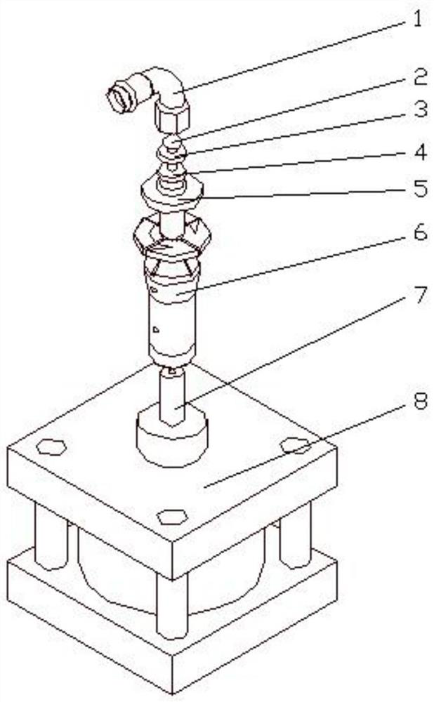
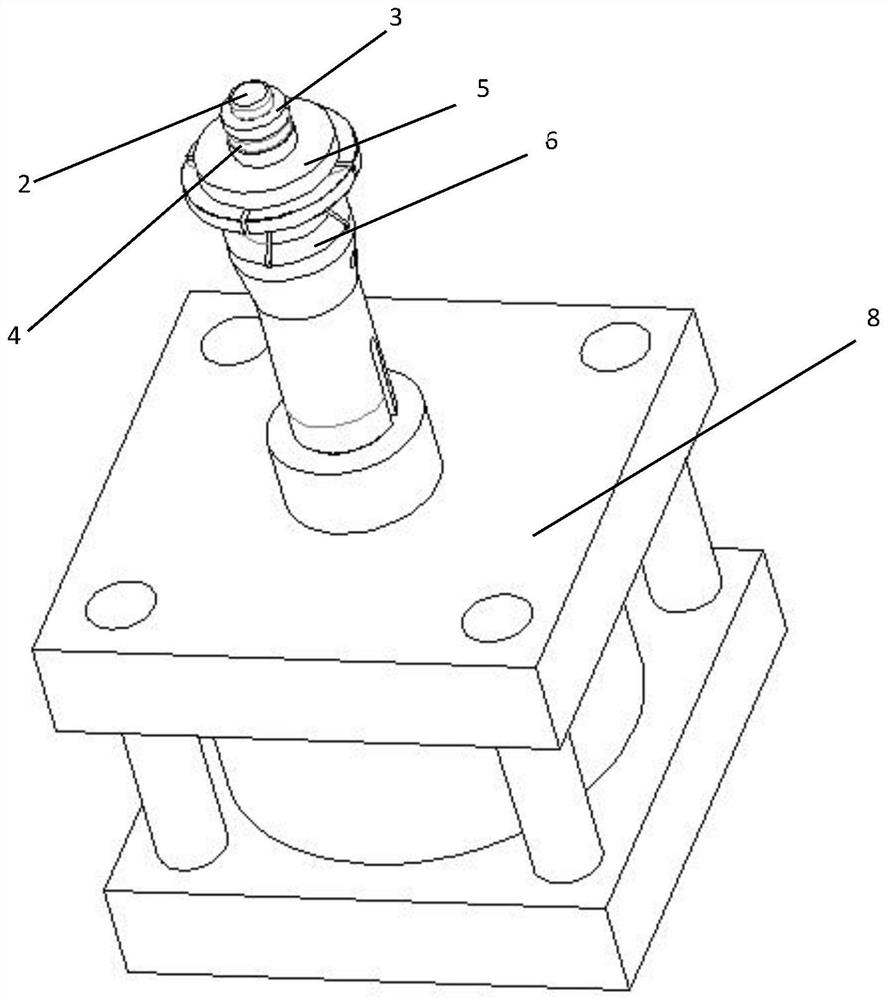
[0018] A welding fixture, including a cylinder 8, a pull rod assembly, a support column and a po...


PUM


Abstract

The invention discloses a welding fixture. The welding fixture comprises a drive assembly, a tie rod assembly, a supporting column and a positioning block assembly; the tie rod assembly is driven to move up and down by the drive assembly and comprises a lock nut and a draw-in bolt, the draw-in bolt is locked by the lock nut; the supporting column is a hollow member for supporting the positioning block assembly; the positioning block assembly is provided with a cushion block, an elastic washer and a positioning block, the cushion block and the elastic washer have relatively small diameters, thepositioning block has a relatively large diameter, and the cushion block, the elastic washer and the positioning block are arranged in sequence from top to bottom; the draw-in bolt penetrates throughthe supporting column, the positioning block, the elastic washer and the cushion block in sequence and can pull the cushion block and the elastic washer to move to the positioning block. The weldingfixture has simple structure, convenient and quick operation and adjustment and stable and reliable clamping of pipe fittings, and can effectively guarantee the welding stability of the pipe fittings;the pipe fittings are positioned accurately, the positioning accuracy is high, and the welding quality can be improved; and the structure design is more scientific and reasonable, and the clamping action is small in the stroke, and the wear is small.

Description

technical field [0001] The invention relates to the technical field of pipe fitting processing equipment, in particular to a welding fixture. Background technique [0002] Pipe transportation is a common transportation method nowadays, mostly used for gas or liquid transportation, and is widely used in modern society. The conveying pipeline of tubular conveying is generally composed of multiple conveying pipes connected and combined, not integrally formed. In order to improve the actual installation efficiency of pipe fittings, in the process of pipe material processing and production, whether it is a straight pipe or a bent pipe, some products are also The welding process of pipe fittings is required in production. Welding is a way of combined connection of metal pipe fittings. During the welding process, the welded metal pipe fittings will absorb a large amount of heat energy and generate high temperature. In addition, in order to ensure the welding quality, it is necessa...

Claims


Application Information

Patent Timeline
IPC IPC(8): B23K37/04B23K101/06
CPCB23K37/0443B23K2101/06
Inventor 徐立地
Owner 广州美亚股份有限公司
Learn More