Re-Orientable Spray Foam Gun Nozzles

a spray foam and nozzle technology, applied in the direction of instruments, heat measurement, measurement devices, etc., can solve the problems of increasing the cost of the dispensing gun in either event, increasing the cost of the dispensing gun, and clogging the static mixer with polyurethane foam or froth formed in the mixer

Inactive Publication Date: 2018-02-15
ICP ADHESIVES & SEALANTS INC
View PDF3 Cites 9 Cited by
  • Summary
  • Abstract
  • Description
  • Claims
  • Application Information

AI Technical Summary

Benefits of technology

[0022]In accordance with the present invention, a plastic spray gun nozzle is described in which the foam spray pattern is orientable from a first position (e.g. vertical spray pattern) to a second position (e.g. horizontal spray pattern) by changing the position of the attached nozzle by rotational movement of the attached nozzle. The plastic spray gun nozzle has a tapered elongated cylindrical bore extending along a longitudinal axis. The cylindrical bore has an expanded cylindrical entrance collar at an ingress end and an opposed egress exit end having a pair of divergent opposed lips at the egress exit end. The entrance collar has an interior and an exterior. The interior of the entrance collar has at least one pair of raised knobs in the expanded cylindrical entrance collar. The interior of the entrance collar removeably mates with an exterior of a front portion of a housing of a spray gun. The exterior of the front portion of the housing of the spray gun has at least two pairs of opposed recessed channels which extend longitudinally from a periphery of an outer edge of the front portion of the housing. The recessed channels transition to a transverse portion extending transverse to a longitudinal axis of the spray gun in a surface of the front portion of the housing of the spray gun. The plastic spray gun nozzle dispenses a pressurized polyurethane foam or a polyurethane froth.

Problems solved by technology

In practice, often the gun operator adjusts the ratio settings to improve gun “performance” with poor results.
The gun cost is increased in either event and “fixing” the ratio setting to a specific formulation prevents interchangeability of the dispensing gun.
While necessary, the dispensing gun's cost is increased.
Because the foam foaming reaction commences when the “A” and “B” components contact one another, it is clear that, once the gun is used, the static mixer will clog with polyurethane foam or froth formed within the mixer.
At least one recurring quality issue facing the disposable polyurethane foam kit industry is the inability of end-users to effectively assess the core chemical temperature of the liquid and gas contents contained therein.
Lower-than-advertised yields carry significant economical consequences for the contractor.
Again, cold chemical temperatures (below recommended) can create off-ratio foam, with the resulting incomplete chemical cure.
However, end-users typically do not condition the kits long enough at the recommended temperature.
For example, kits stored in an unconditioned warehouse or insulation truck in the winter months may have a core chemical temperature of only ˜40° F. If dispensed without being conditioned for a sufficient amount of time, the result is foam of very poor physical quality and appearance.
Also, improper chemical cure will most likely occur (unbalanced ratio of “A” to “B” chemical, which is typically 1:1 by weight).
This can require the user to hold the dispensing gun in uncomfortable positions or at awkward angles in order to orient the straight line pattern of the dispensed foam in the desired direction.

Method used


Image

  • Re-Orientable Spray Foam Gun Nozzles
  • Re-Orientable Spray Foam Gun Nozzles
  • Re-Orientable Spray Foam Gun Nozzles

Examples


Embodiment Construction

[0044]The best mode for carrying out the invention will now be described for the purposes of illustrating the best mode known to the applicant at the time of the filing of this patent application. The examples and figures are illustrative only and not meant to limit the invention, which is measured by the scope and spirit of the claims.

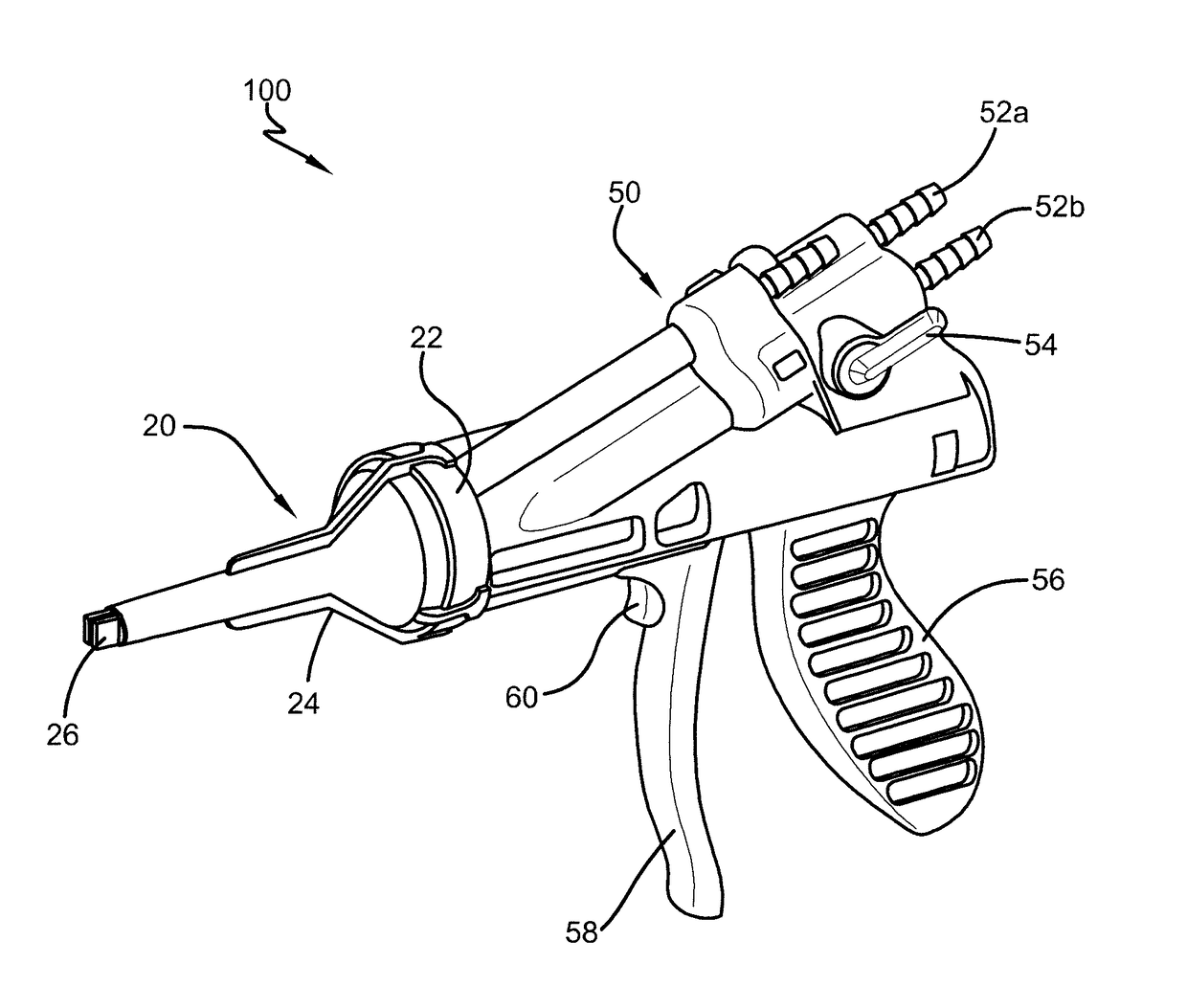
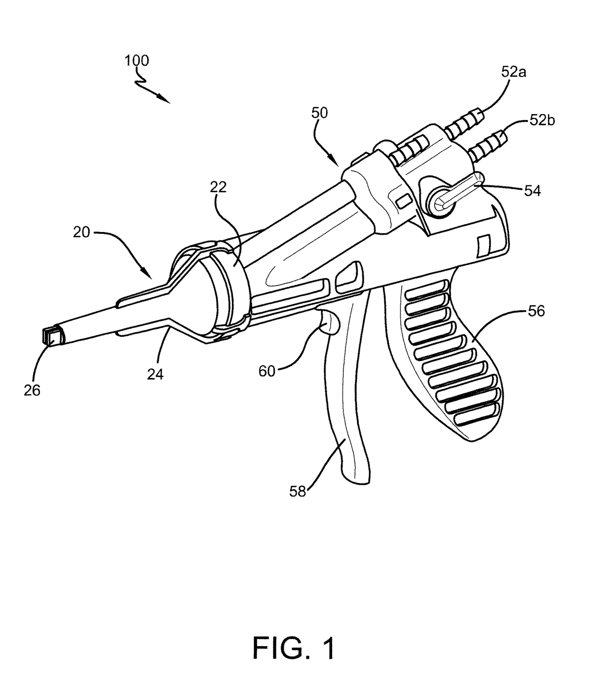
[0045]For consistency in terminology, when describing the plastic spray gun nozzle 20 or the spray gun 50, “longitudinal” will refer to the direction of the dispensing gun along the long axis of dispensing passage; “transverse” will refer to the direction perpendicular to a longitudinal axis.

[0046]The invention relates to, as shown in perspective views in FIGS. 1 & 2, a plastic spray gun nozzle 20 which can be used in dispensing a pressurized polyurethane foam or a polyurethane froth. As displayed by the mated assembly 100, the nozzle 20 removeably mates with an exterior of front portion 62 of a housing of spray gun body 50. As illustrated, spray gun ...


PUM

PropertyMeasurementUnit
pressureaaaaaaaaaa
diameteraaaaaaaaaa
temperatureaaaaaaaaaa

Abstract

The invention pertains to a plastic spray gun nozzle having an orientable spray pattern achieved by rotational movement of the repositionable plastic nozzle.

Description

TECHNICAL FIELD[0001]The invention described herein pertains generally to spray foam gun nozzles.BACKGROUND OF THE INVENTION[0002]This invention is particularly suited for in-situ applications of liquid chemicals mixed and dispensed as a spray or a foam and more specifically, to in-situ application of polyurethane foam or froth and optionally, the measurement of the temperature of the chemicals used therewith. In-situ applications for polyurethane foam have continued to increase in recent years extending the application of polyurethane foam beyond its traditional uses in the packaging, insulation and molding fields. For example, polyurethane foam is being used with increasing frequency as a sealant in the building trades for sealing spaces between windows and door frames and the like and as an adhesive for gluing flooring, roof tiles, and the like.[0003]Polyurethane foam for in-situ applications is typically supplied as a “one-component” froth foam or a “two-component” froth foam in...

Claims


Application Information

Patent Timeline
Patent Type & Authority Applications(United States)
IPC IPC(8): B05B7/04G01K11/16B05B1/02B05B12/00B05B7/00B05B7/02
CPCB05B7/0408B05B7/0025G01K11/165B05B1/02B05B12/002B05B7/025B05B1/042B05B7/0018B05B15/652B05B15/65B05B12/0026
Inventor GANTENBEIN, STEFAN K.CLINE, MOJGANMIEDZA, KRZYSZTOF P.MIZER, SCOTT E.MILLIFF, BRIAN T.MACZUZAK, MICHAEL J.
Owner ICP ADHESIVES & SEALANTS INC
Why Eureka
Try Eureka