Ventilated Seat Cushion

a seat cushion and ventilating technology, applied in the field of seats, can solve the problems of inefficiency of thermal and mass, the inability to ventilate moisture and air,

Active Publication Date: 2018-02-15
FORD GLOBAL TECH LLC
View PDF1 Cites 37 Cited by
  • Summary
  • Abstract
  • Description
  • Claims
  • Application Information

AI Technical Summary

Problems solved by technology

This current construction prohibits ventilation of moisture and air at the human skin layer int

Method used


Image

  • Ventilated Seat Cushion
  • Ventilated Seat Cushion
  • Ventilated Seat Cushion

Examples


Embodiment Construction

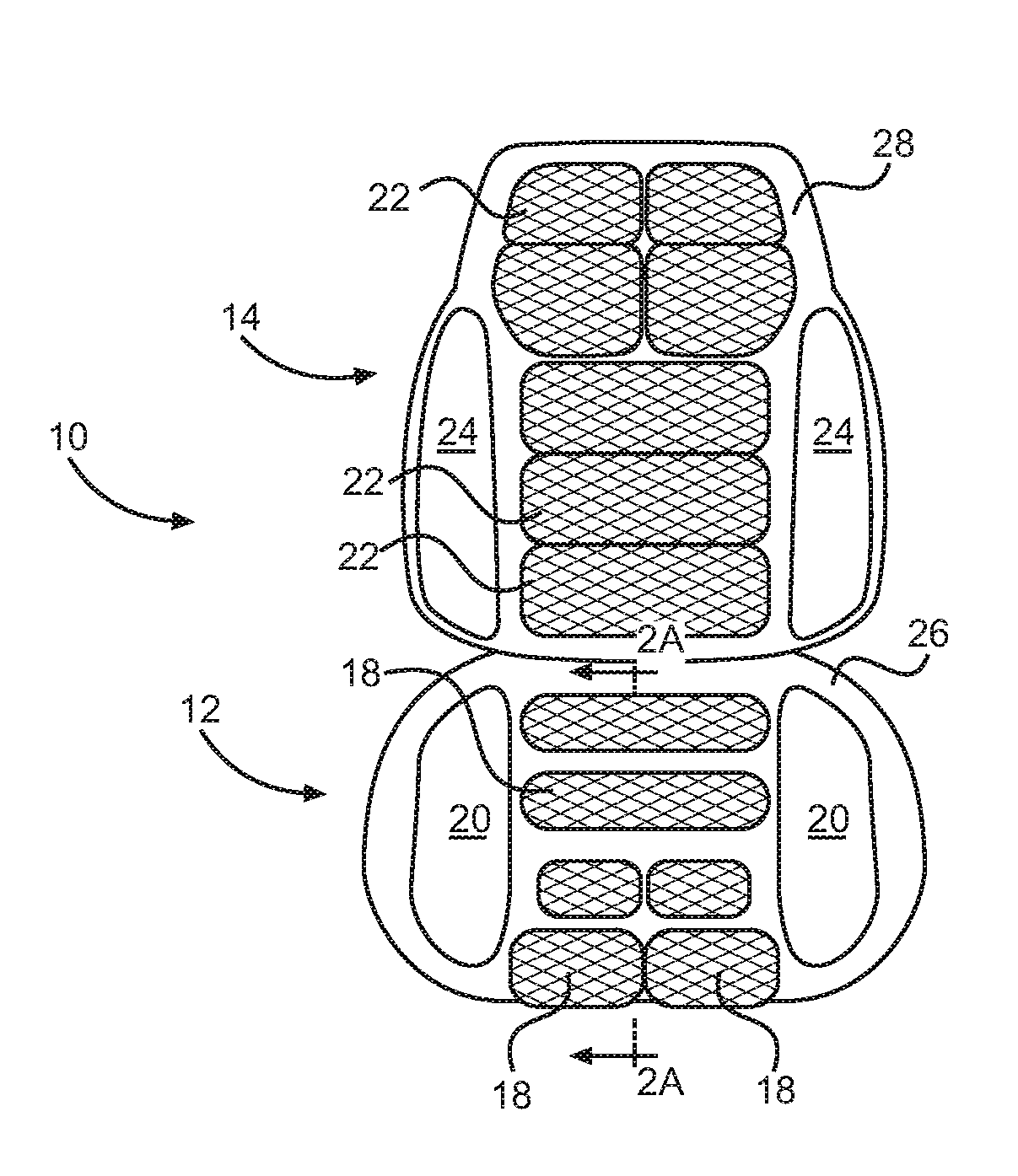
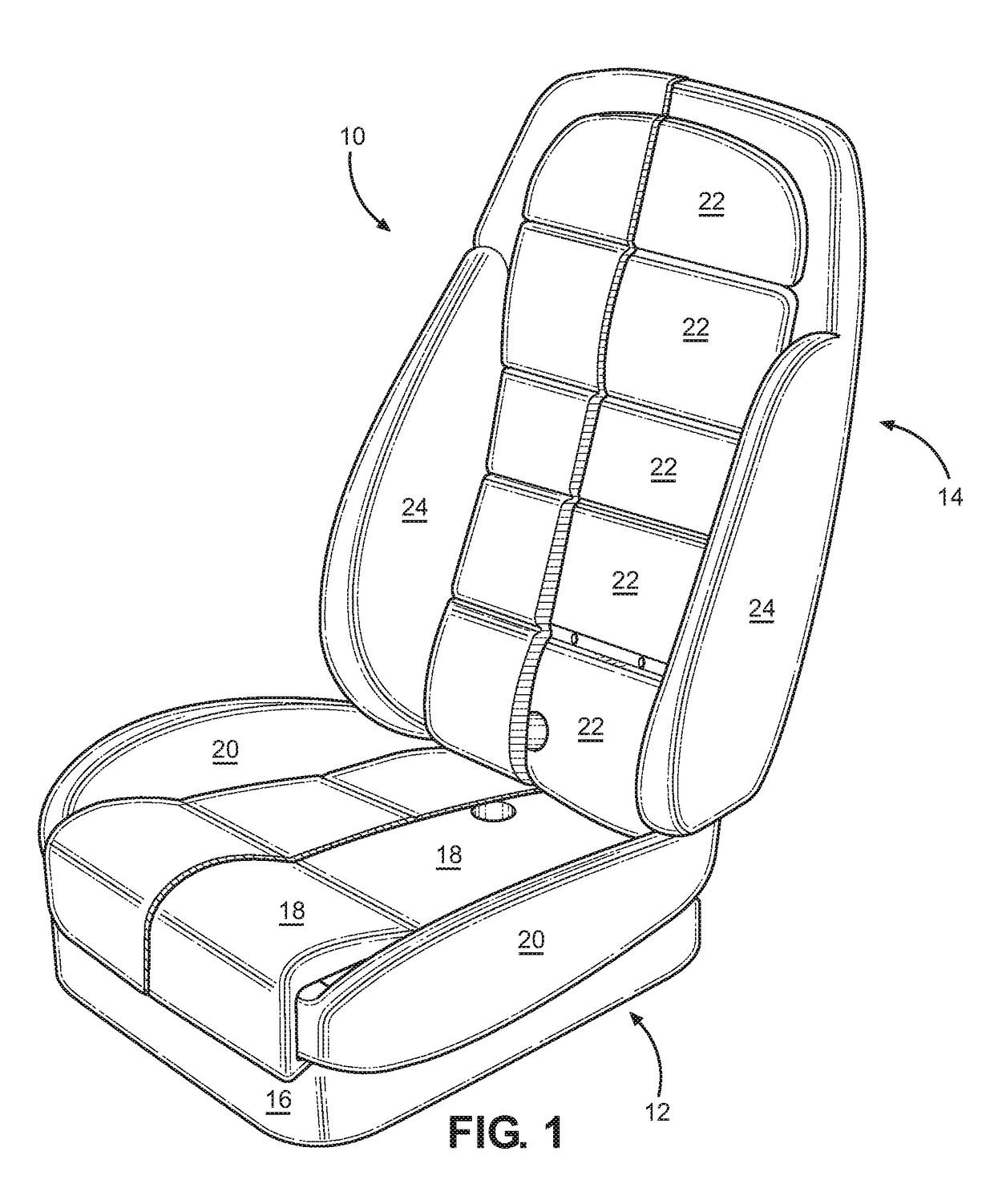
[0012]Referring to FIGS. 1A and 1B, a typical vehicle seat 10 includes a seat bottom 12 and seat back 14 oriented at an angle relative to the seat bottom 12 as known in the art. As also known in the art, the seat bottom 12 may be mounted to a base 16 that may include one or more motors for actuating the seat. One or more temperature modulating elements, e.g. heating and cooling elements may be embedded in the seat bottom 12 and / or seat back 14 as known in the art.

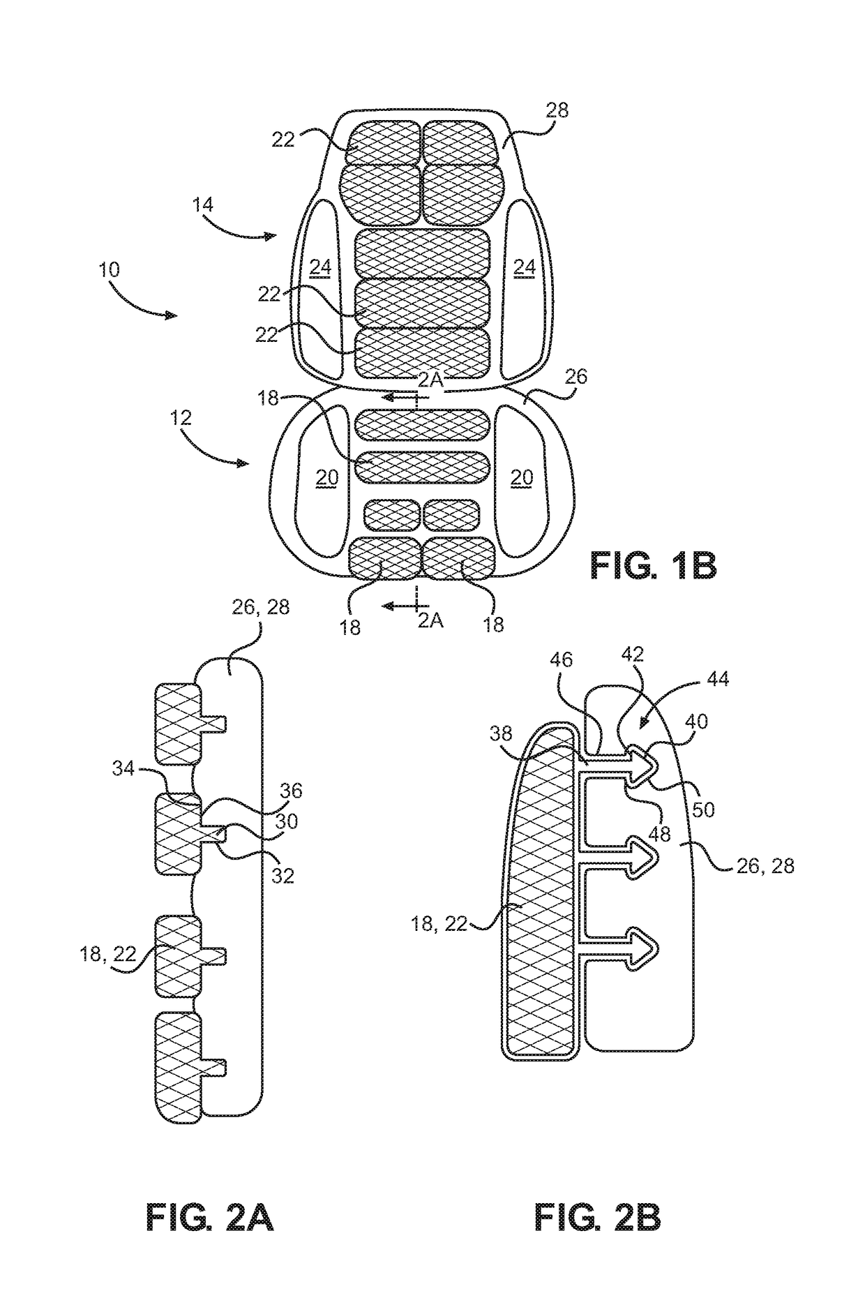
[0013]A seat 10 in accordance with the embodiments disclosed herein may include a seat bottom 12 having a plurality of cushions 18 defining a seating surface and lateral bolsters 20 extending upwardly and outwardly from the seating surface at an angle. Likewise, the seat back may include a plurality of cushions 22 defining a back support surface. Lateral bolsters 24 may extend forwardly and outwardly from the back support surface. In some embodiments, the cushions 18, 22 are formed of a 3D (three-dimensionally) printed latt...


PUM

PropertyMeasurementUnit
Widthaaaaaaaaaa
Widthaaaaaaaaaa
Structureaaaaaaaaaa

Abstract

A seat includes one or more cushions secured to a shell. The cushions include a 3D printed lattice of repeating cells. The cells may include nodes interconnected by branches. The nodes may be arranged in a cubic, parallelepiped, diamond, or other arrangement. The branches may extend directly between nodes or may be bent. The branches may extend from each node to an adjacent node that is closest to its point of attachment to the each node or the branches may be curved or bent to secure to a different adjacent node. The 3D printed lattice may include 3D printed barbs formed thereon that engage receptacles in the seat shell. The 3D printed lattice may be printed with a groove that engages a fastening structure on a cover or a separate fastening element. The cover may be a perforated sheet of material or fabric.

Description

BACKGROUNDField of the Invention[0001]This invention relates to cushions for a seat of a vehicle or other applications.Background of the Invention[0002]Automotive seats are typically made of molded foam pads wrapped with either vinyl or leather outer cover. This current construction prohibits ventilation of moisture and air at the human skin layer interfacing with it. Even fabric-covered foam is insulative and prevents free air circulation. Such inefficiency of thermal and mass (e.g., sweat) transfer causes discomfort.[0003]The systems and methods described herein provide an improved approach to the design and manufacture of cushions for use in vehicle seat bottoms, backs, headrests, or for any other application where cushions may be used.BRIEF DESCRIPTION OF THE DRAWINGS[0004]In order that the advantages of the invention will be readily understood, a more particular description of the invention briefly described above will be rendered by reference to specific embodiments illustrate...

Claims


Application Information

Patent Timeline
IPC IPC(8): B60N2/56B29C67/00B29D99/00B60N2/64
CPCB60N2/56B60N2/64B29K2995/0065B29D99/0092B29K2995/0054B29C67/0051A47C7/742B60N2/62B33Y80/00B60N2/5642B60N2/7017B29L2031/58B60N2/7005
Inventor BAEK, HYUNG MINBOCCUCCIA, DANIEL
Owner FORD GLOBAL TECH LLC
Why Eureka
Try Eureka