
Core material for balanced rotor blade

a rotor blade and core material technology, applied in the field of rotor blades, can solve the problems of time-consuming and conventional procedures for balancing the rotor blade assembly

Active Publication Date: 2018-02-15
SIKORSKY AIRCRAFT CORP
View PDF2 Cites 11 Cited by
  • Summary
  • Abstract
  • Description
  • Claims
  • Application Information

AI Technical Summary

Benefits of technology

The technical effect of this patent is that it describes how to make a rotor bladder without requiring any adhesive to meet its weight requirements.

Problems solved by technology

This patent discusses how important it is to make sure that rotor blades used on helicopters are properly balanced. If they aren't, there could be too much movement during operation, causing damage and potentially even injury. Currently, checking and balancing individual blades takes up a lot of time. So, this technical problem is finding ways to quickly and accurately check and balance multiple rotor blades at once.

Method used


Image

  • Core material for balanced rotor blade
  • Core material for balanced rotor blade
  • Core material for balanced rotor blade

Examples


Embodiment Construction

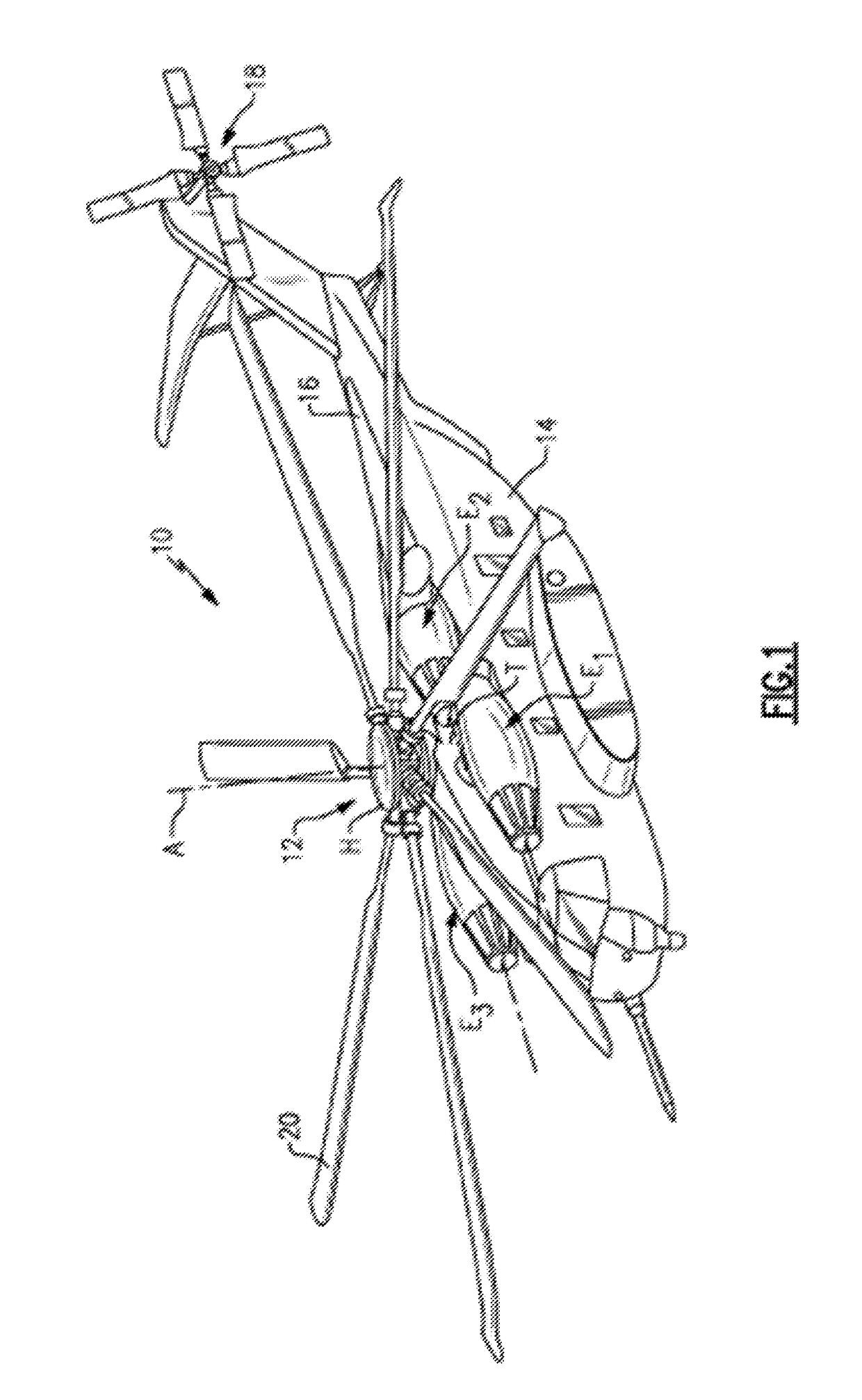
[0034]FIG. 1 schematically illustrates a rotary-wing aircraft 10 having a main rotor system 12. The aircraft 10 includes an airframe 14 having an extending tail 16 which mounts a tail rotor system 18, such as an anti-torque system. The main rotor system 12 is driven about an axis of rotation A through a main gearbox (illustrated schematically at T) by one or more engines E. The main rotor system 12 includes a plurality of rotor blade assemblies 20 mounted to a rotor hub assembly H. Although a particular helicopter configuration is illustrated and described in the disclosed non-limiting embodiment, other configurations and / or machines, such as high speed compound rotary wing aircraft with supplemental translational thrust systems, dual contra-rotating, coaxial rotor system aircraft, turbo-props, tilt-rotors and tilt-wing aircraft, will also benefit from the present invention.

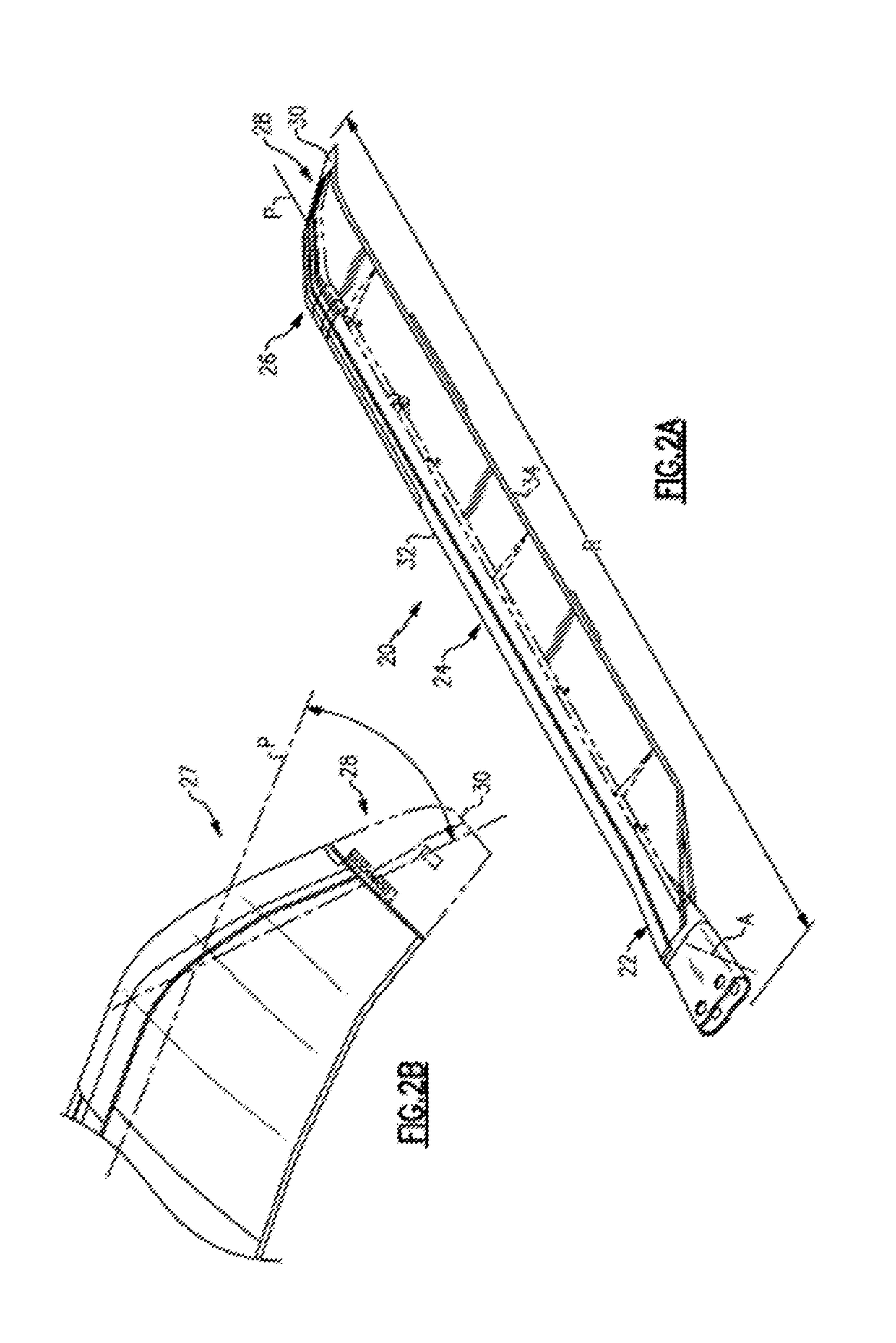
[0035]Referring to FIGS. 2A and 2B, each rotor blade assembly 20 of the main rotor system 12 generally include...


PUM

PropertyMeasurementUnit
Weightaaaaaaaaaa
Thicknessaaaaaaaaaa
Densityaaaaaaaaaa

Abstract

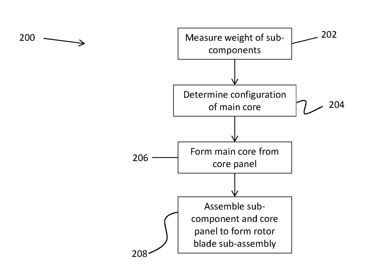
A method of forming a balanced rotor blade assembly includes measuring a weight of a plurality of sub-components of the rotor blade assembly excluding a core. A configuration of a core of the rotor blade assembly is determined. In combination, the core and the plurality of sub-components achieve a target weight distribution and moment. The core is then fabricated and assembled with the plurality of sub-components to form a rotor blade sub-assembly.

Description


Claims


Application Information

Patent Timeline
Owner SIKORSKY AIRCRAFT CORP
Learn More