Ocular lens and imaging apparatus

a technology which is applied in the field of optical lenses and imaging apparatus, can solve the problems of not being able to achieve the magnification of the field of view, and achieve the effects of satisfactory optical performance, wide apparent field of view, and high eye-poin

Active Publication Date: 2018-02-22
FUJIFILM CORP
View PDF2 Cites 3 Cited by
  • Summary
  • Abstract
  • Description
  • Claims
  • Application Information

AI Technical Summary

Benefits of technology

[0025]According to the present invention, in a lens system configured as three groups of positive, positive and positive lens or positive, negative and positive lens in order from the observation object side, since the configuration of each lens group is set specifically and suitably, and satisfies predetermined conditional expressions, it is possible to provide an ocular lens having a high eye-point, a wide apparent field of view, and satisfactory optical performance, and an imaging apparatus including this ocular lens.

Problems solved by technology

However, it has not been easy to achieve the magnification of the field of view in a state of being set to have a high eye-point.

Method used


Image

  • Ocular lens and imaging apparatus
  • Ocular lens and imaging apparatus
  • Ocular lens and imaging apparatus

Examples


example 1

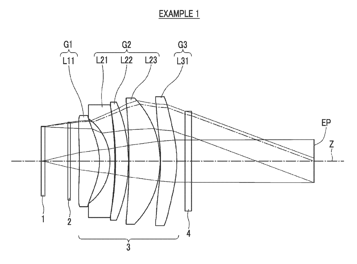
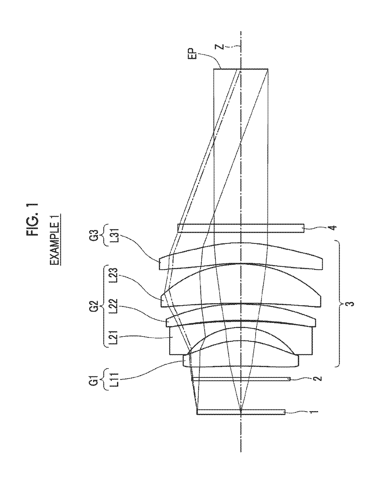
[0074]A lens configuration and an optical path of an ocular lens of Example 1 are shown in FIG. 1, and a method of illustration thereof and the configuration thereof are as described, as the example shown in FIG. 1. Therefore, the repeated description thereof will be partially omitted herein. The ocular lens of Example 1 consists of a first lens group G1 having a positive refractive power, a second lens group G2 having a positive refractive power, and a third lens group G3 having a positive refractive power, in order from the object side. The second lens group G2 consists of a meniscus-shaped lens L21 having a negative refractive power with the convex surface toward the eye-point side and two meniscus-shaped lenses L22 and L23 having a positive refractive power with the convex surface toward the eye-point side, in order from the object side.

[0075]Table 1 shows basic lens data of the ocular lens of Example 1, Table 2 shows specifications, and Table 3 shows aspherical coefficients. Th...

example 2

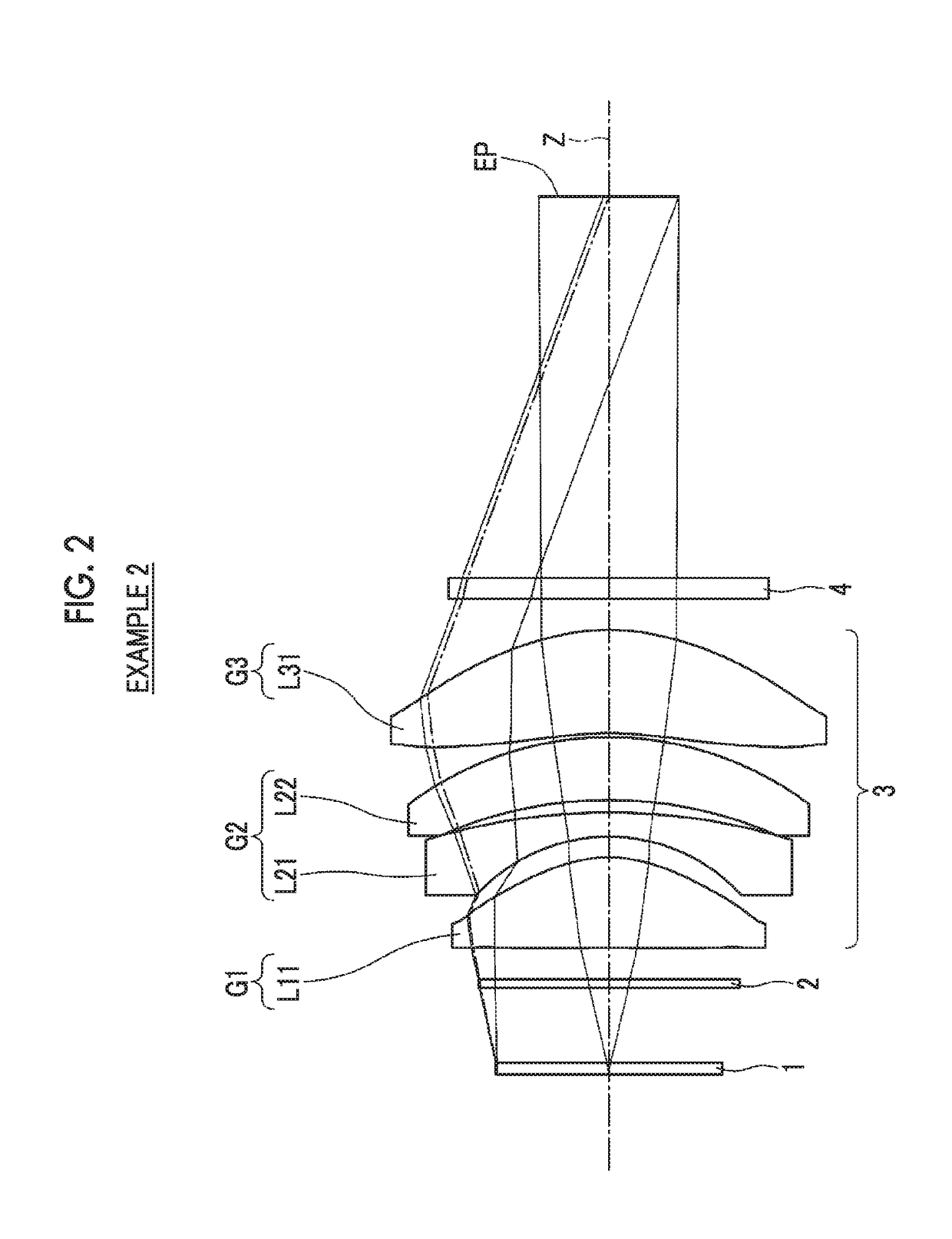
[0086]A lens configuration and an optical path of an ocular lens of Example 2 are shown in FIG. 2. The ocular lens of Example 2 consists of a first lens group G1 having a positive refractive power, a second lens group G2 having a negative refractive power, and a third lens group G3 having a positive refractive power, in order from the object side. the second lens group G2 consists of a meniscus-shaped lens L21 having a negative refractive power with the convex surface toward the eye-point side and a meniscus-shaped lens L22 having a positive refractive power with the convex surface toward the eye-point side, in order from the object side.

[0087]Table 4 shows basic lens data of the ocular lens of Example 2, Table 5 shows specifications, Table 6 shows aspherical coefficients, and FIG. 5 shows a diagram of aberrations. The values shown in Table 5 correspond to a case where the diopter scale is −1 diopter, and the ocular lens of Example 2 is configured such that the adjustment of the dio...

example 3

[0088]A lens configuration and an optical path of an ocular lens of Example 3 are shown in FIG. 3. The ocular lens of Example 3 consists of a first lens group G1 having a positive refractive power, a second lens group G2 having a negative refractive power, and a third lens group G3 having a positive refractive power, in order from the object side. The second lens group G2 consists of a meniscus-shaped lens L21 having a negative refractive power with the convex surface toward the eye-point side, a biconcave lens L22, and a biconvex lens L23, in order from the object side.

[0089]Table 7 shows basic lens data of the ocular lens of Example 3, Table 8 shows specifications, Table 9 shows aspherical coefficients, and FIG. 6 shows a diagram of aberrations. The values shown in Table 8 correspond to a case where the diopter scale is −1 diopter, and the ocular lens of Example 3 is configured such that the adjustment of the diopter scale in a range of −4 diopter to +2 diopter can be performed by...


PUM


Abstract

An ocular lens consists of a positive first lens group, a positive or negative second lens group, and a positive third lens group, in order from an observation object side. The first lens group consists of a positive meniscus lens with a convex surface toward an eye-point side. The second lens group includes a negative lens and a positive lens, and the number of lenses constituting the second lens group is three or less. The third lens group consists of a positive meniscus lens with a convex surface toward the eye-point side. The following conditional expression relating to a focal length of the whole system and a distance on an optical axis from a lens surface closest to the observation object side to a lens surface closest to the eye-point side is satisfied: 0.8<f/TL<1.1.

Description

CROSS-REFERENCE TO RELATED APPLICATIONS[0001]The present application claims priority under 35 U.S.C. §119 to Japanese Patent Application No. 2016-161204, filed on Aug. 19, 2016. The above application is hereby expressly incorporated by reference, in its entirety, into the present application.BACKGROUND OF THE INVENTION1. Field of the Invention[0002]The present invention relates to an ocular lens and an imaging apparatus, and more specifically relates to an ocular lens suitable for magnification observation of an image displayed on an image display device, and an imaging apparatus having this ocular lens mounted thereon.2. Description of the Related Art[0003]Hitherto, ocular lenses for magnifying an image displayed on an image display device such as a liquid crystal display device and observing the image with the naked eye have been used in a viewfinder of an imaging apparatus such as a digital camera. There has been a demand for such an ocular lens to be small in size and to be high...

Claims


Application Information

Patent Timeline
Patent Type & Authority Applications(United States)
IPC IPC(8): G03B13/06H04N5/232G03B17/20G03B13/16
CPCG03B13/06H04N5/23293G03B13/16G03B17/20H04N5/23216G02B25/001H04N23/63G02B9/12H04N23/62
Inventor MIYAGISHIMA, SHUNSUKESAITO, HIROKI
Owner FUJIFILM CORP
Why Eureka
Try Eureka