Eureka AIR delivers breakthrough ideas for toughest innovation challenges, trusted by R&D personnel around the world.

Light-emitting device, lighting device, and method of manufacturing light-emitting device

Inactive Publication Date: 2018-03-01
PANASONIC INTELLECTUAL PROPERTY MANAGEMENT CO LTD
View PDF1 Cites 4 Cited by
  • Summary
  • Abstract
  • Description
  • Claims
  • Application Information

AI Technical Summary

Benefits of technology

The patent aims to provide a light-emitting device that prevents uneven lighting. This means that the device can produce light in a way that ensures that each part of the device emits light in a balanced manner. The invention can be used in both lighting devices and light-emitting devices. This patent is useful for R&D personnel who are trying to create consistent and uniform lighting.

Problems solved by technology

However, with the conventional light-emitting device, even when the light-emitting element is sealed using the sealant after a reflow process in which the light-emitting element is placed on the adhesive, the relative positioning of the light-emitting element and the sealant shifts, leading to non-uniform emission of light by the light-emitting device.

Method used


Image

  • Light-emitting device, lighting device, and method of manufacturing light-emitting device
  • Light-emitting device, lighting device, and method of manufacturing light-emitting device
  • Light-emitting device, lighting device, and method of manufacturing light-emitting device

Examples


embodiment 1

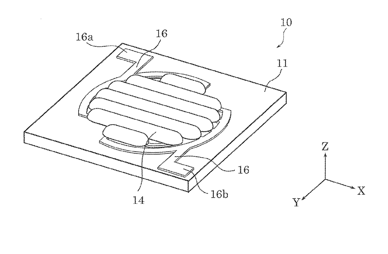
[0022]Hereinafter, light-emitting device 10 according to an embodiment of the present disclosure will be described.

(Configuration)

[0023]First, light-emitting device 10 according to this embodiment will be described with reference to FIG. 1.

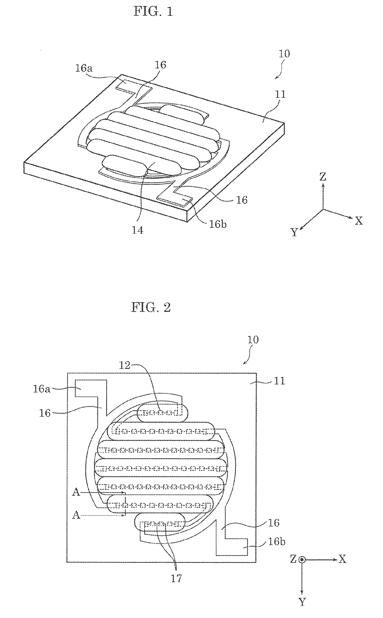
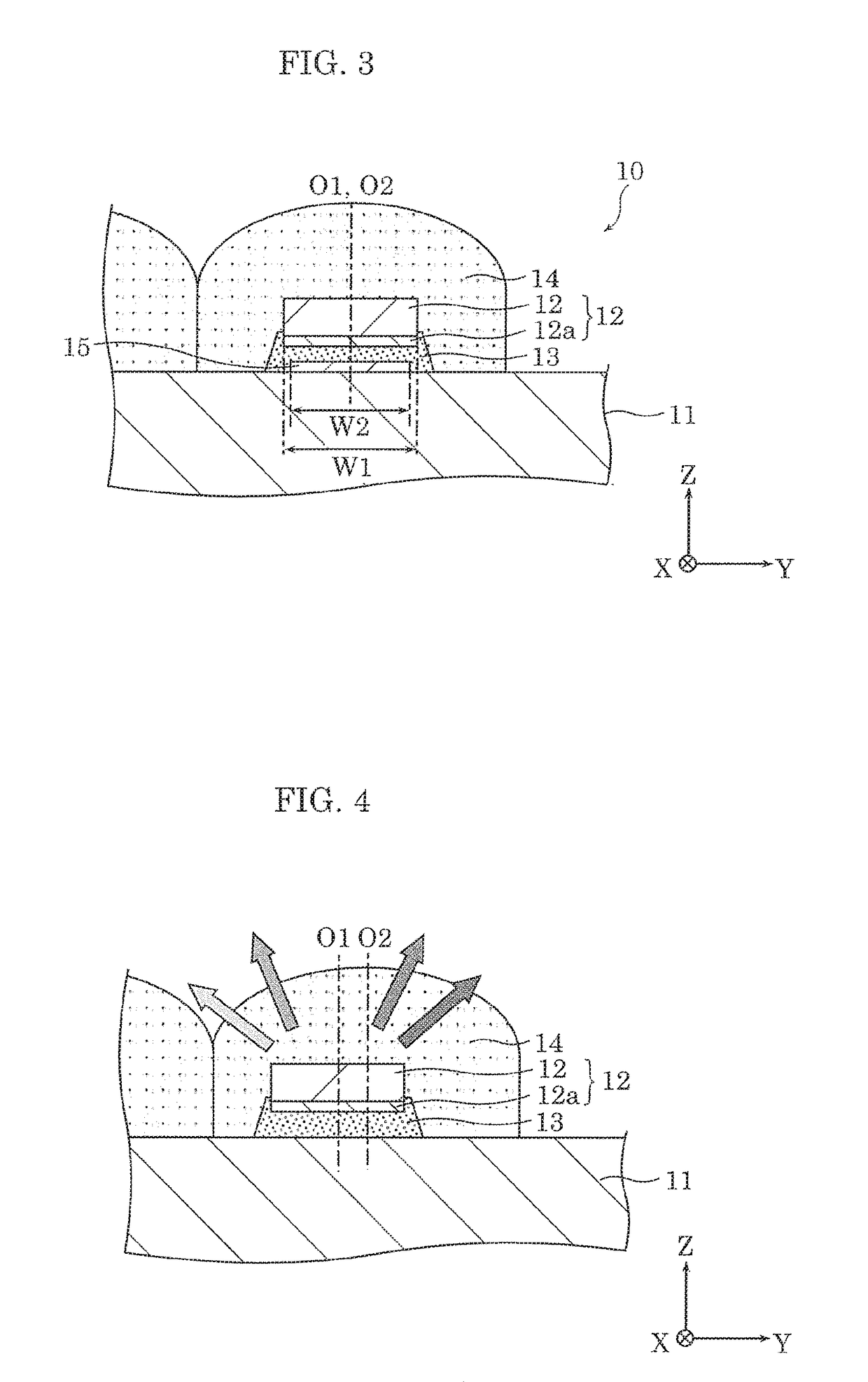
[0024]FIG. 1 is an external perspective view of light-emitting device 10 according to this embodiment. FIG. 2 is a plan view of light-emitting device 10 according to this embodiment. FIG. 3 is an enlarged cross sectional view of part of light-emitting device 10, taken at line A-A in FIG. 2. FIG. 3 is a plan view of light-emitting device 10 according to this embodiment. Note that the illustration of bonding wires 17 is omitted from FIG. 3, FIG. 4, and FIG. 8.

[0025]In FIG. 1, with respect to light-emitting device 10, the LED chip optical axis direction is defined as the Z axis positive direction, a direction orthogonal to the Z axis positive direction is defined as the X axis positive direction, and a direction orthogonal to both the X axis positive...

embodiment 2

[0108]Next, lighting device 200 according to this embodiment will be described with reference to FIG. 9 and FIG. 10.

[0109]FIG. 9 is a cross sectional view of lighting device 200 according to this embodiment. FIG. 10 is a perspective view of lighting device 200 according to this embodiment.

(Configuration)

[0110]First, the configuration of lighting device 200 according to this embodiment will be described.

[0111]As illustrated in FIG. 9 and FIG. 10, lighting device 200 according to this embodiment is, for example, a recessed lighting device such as a downlight that is installed recessed in the ceiling of, for example, a home and emits light downward (onto the floor or a wall, for example).

[0112]Lighting device 200 includes light-emitting device 10. Lighting device 200 further includes: a fixture body having an approximately bottomed tubular shape, configured as a result of base portion 210 and frame portion 220 being coupled together; reflective plate 230 disposed on the fixture body; a...


PUM


Abstract

A light-emitting device is provided. The light-emitting device includes a substrate and a base on or defined by the substrate. A light-emitting element is above the base. An adhesive fixes the light-emitting element above the base. A sealant seals the light-emitting element and includes a phosphor that emits fluorescent light when stimulated by light from the light-emitting element. In a plan view of the base and the light-emitting element, a span of at least part of the base is less than or equal to a corresponding span of the light-emitting element.

Description

CROSS REFERENCE TO RELATED APPLICATION[0001]This application claims the benefit of priority of Japanese Patent Application Number 2016-164146 filed on Aug. 24, 2016, the entire content of which is hereby incorporated by reference.BACKGROUND1. Technical Field[0002]The present disclosure relates to: a light-emitting device including a substrate and a light-emitting element mounted on the substrate; a lighting device including the light-emitting device; and a method of manufacturing a light-emitting device.2. Description of the Related Art[0003]A conventional light-emitting body including a substrate, a semiconductor light-emitting element mounted on the substrate, a light-transmissive sealing resin that covers the semiconductor light-emitting element, and an adhesive that mounts the semiconductor light-emitting element to the substrate is known (for example, see Japanese Unexamined Patent Application Publication No. 2013-4704).SUMMARY[0004]However, with the conventional light-emitting...

Claims


Application Information

Patent Timeline
IPC IPC(8): F21K9/64F21K9/90
CPCF21K9/90F21K9/64H01L25/0753H01L33/502H01L33/54H01L33/62
Inventor TAKEHARA, KOSUKE
Owner PANASONIC INTELLECTUAL PROPERTY MANAGEMENT CO LTD
Why Eureka
Eureka Blog
Learn More