Umbrella

a technology of ribs and cuffs, applied in the field of cuffs, can solve the problems of troublesome process and long time-consuming process of rib arrangement, and achieve the effect of convenient and fast closing

Inactive Publication Date: 2018-03-08
CHO CHIN HSING
View PDF0 Cites 2 Cited by
  • Summary
  • Abstract
  • Description
  • Claims
  • Application Information

AI Technical Summary

Benefits of technology

[0005]It is the primary objective of the present invention to provide an umbrella that can be neatly closed with ease.

Problems solved by technology

However, the arrangement of the ribs is a troublesome process that takes a long period of time.

Method used


Image

  • Umbrella
  • Umbrella
  • Umbrella

Examples


Embodiment Construction

[0023]In the following description referring to the FIGS. 1 through 5, similar elements will be given identical numbers for briefness and clarity.

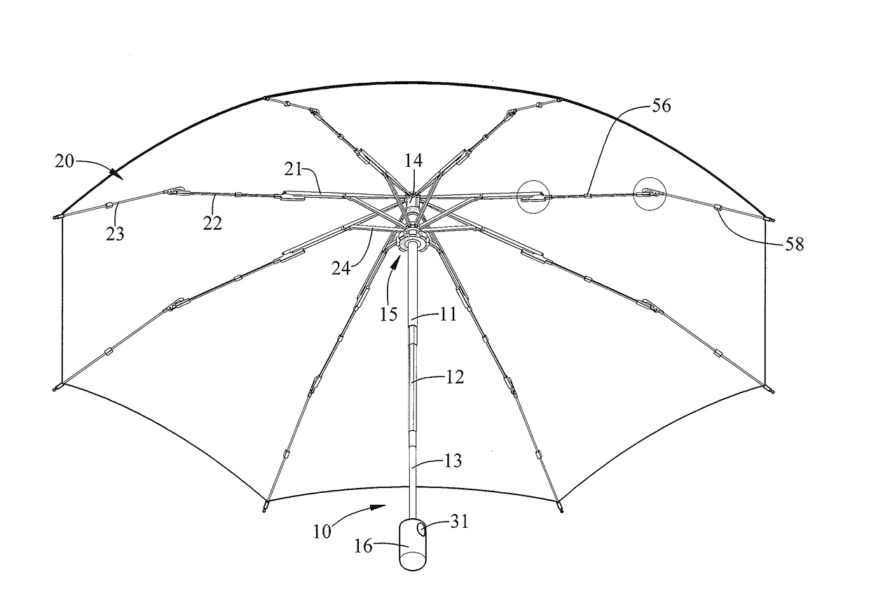
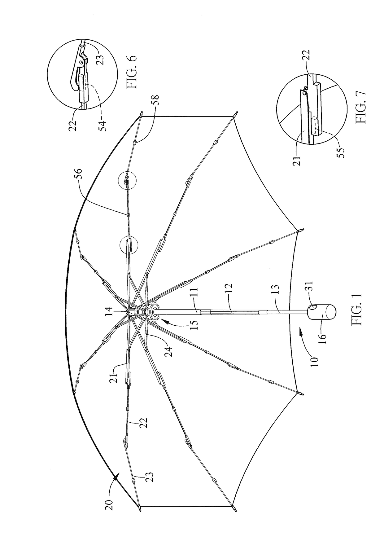
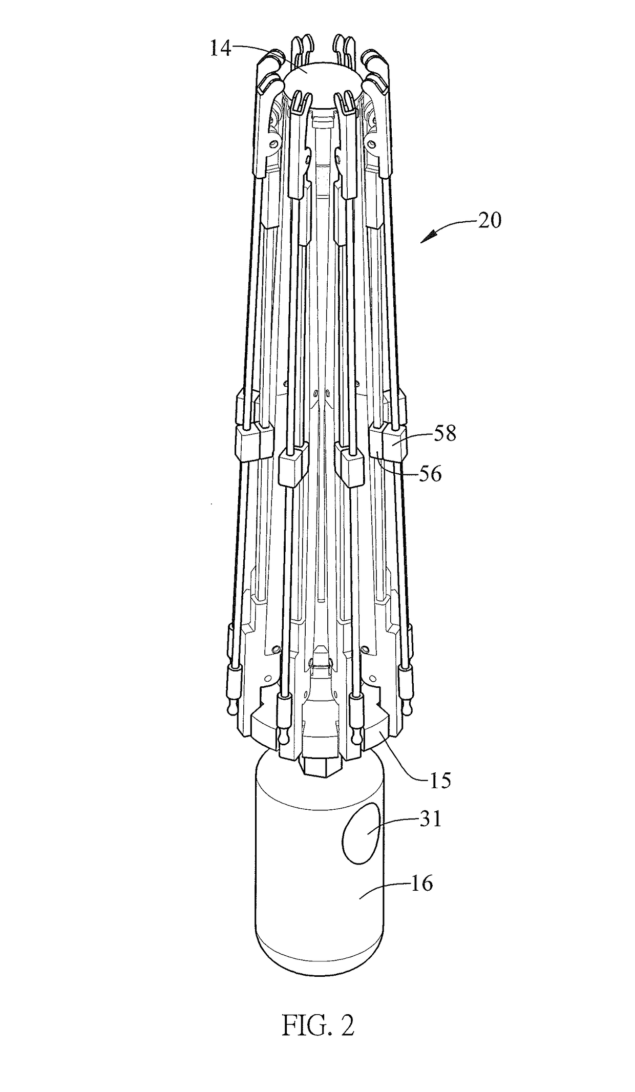
[0024]An umbrella includes a shaft 10, long ribs 20, short ribs 24, a controller unit (not numbered) and rib-collapsing units (not numbered) according to the preferred embodiment of the present invention. Each of the rib-collapsing units is used to collapse and keep a corresponding one of the long ribs 20 near the shaft 10.

[0025]The shaft 10 includes an upper tube 11, a middle tube 12 and a lower tube 13. The upper tube 11, the middle tube 12 and the lower tube 13 are telescopically connected to one another. Hence, the length of the shaft 10 is adjustable. A cap 14 is non-movably connected to an upper portion of the upper tube 11. A runner 15 is movably connected to the upper tube 11. A handle 16 is non-movably connected to a lower portion of the lower tube 13. A user can hold the umbrella by the handle 16.

[0026]Each of the long ribs 20 in...


PUM


Abstract

An umbrella includes a shaft, a cap connected to the shaft, a runner movable on the shaft, long and short ribs, a controller unit and rib-collapsing units. The runner includes recesses. Each of the long ribs includes upper, middle and lower sections. The short ribs connect the upper sections of the long ribs to the runner. The controller unit is operable to allow the long ribs to stretch and collapse. Each of the rib-collapsing units includes a cap magnet connected to the cap, a runner magnet inserted in a corresponding one of the recesses and two middle-section magnets. The first middle-section magnet is connected to the middle section of a corresponding one of the long ribs and adapted for attraction to the cap magnet. The second middle-section magnet is connected to the middle section of a corresponding one of the long ribs and adapted for attraction to the runner magnet.

Description

BACKGROUND OF INVENTION1. Field of Invention[0001]The present invention relates to an umbrella and, more particularly, to an umbrella that includes rib-collapsing units.2. Related Prior Art[0002]A conventional umbrella includes a panel, a shaft, ribs and a controller unit. The panel is connected to the ribs. The shaft includes an upper tube, a middle tube and a lower tube. A cap is non-movably connected to an upper portion of the upper tube. A runner is movably connected to the upper tube. A handle is connected to a lower portion of the lower tube. Each of the ribs includes upper, lower and middle sections pivotally connected to one another. An end of the upper section of each of the ribs is pivotally connected to the cap while an end of the lower section of the same is pivotally connected to the runner. The controller unit is inserted in the shaft. The controller unit includes a button located on the handle. The button is operable to instruct the controller unit to allow the ribs t...

Claims


Application Information

Patent Timeline
Patent Type & Authority Applications(United States)
IPC IPC(8): A45B19/10
CPCA45B19/10A45B19/00A45B25/02
Inventor CHO, CHIN-HSINGCHEN, WEI-JENLIN, CHANG-CHENGCHEN, MEI-LINGCUI, MENG-JIEYU, YANG
Owner CHO CHIN HSING
Why Eureka
Try Eureka