
Fuel injector with direct needle control and servo valve assistance

一种燃料喷射、喷射器的技术,应用在燃料喷射装置、特殊燃料喷射装置、装料系统等方向,能够解决燃料喷射器结构尺寸大等问题

Inactive Publication Date: 2009-08-05
ROBERT BOSCH GMBH
View PDF1 Cites 6 Cited by
  • Summary
  • Abstract
  • Description
  • Claims
  • Application Information

AI Technical Summary

Problems solved by technology

This results in a large structural size of the fuel injector

Method used


Image

  • Fuel injector with direct needle control and servo valve assistance
  • Fuel injector with direct needle control and servo valve assistance
  • Fuel injector with direct needle control and servo valve assistance

Examples


no. 1 approach

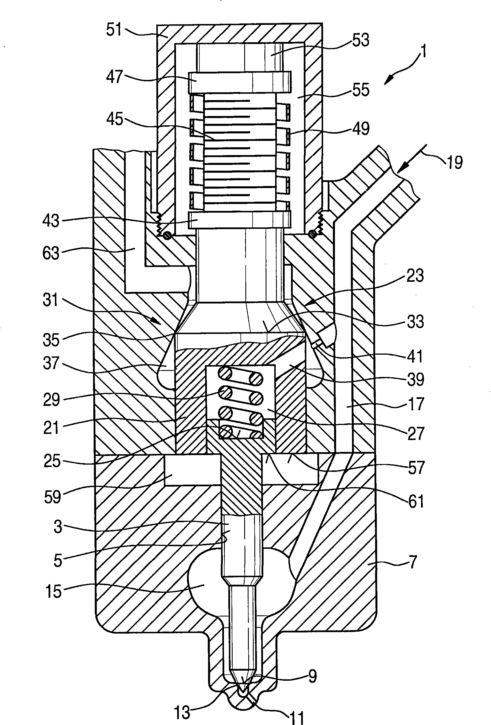
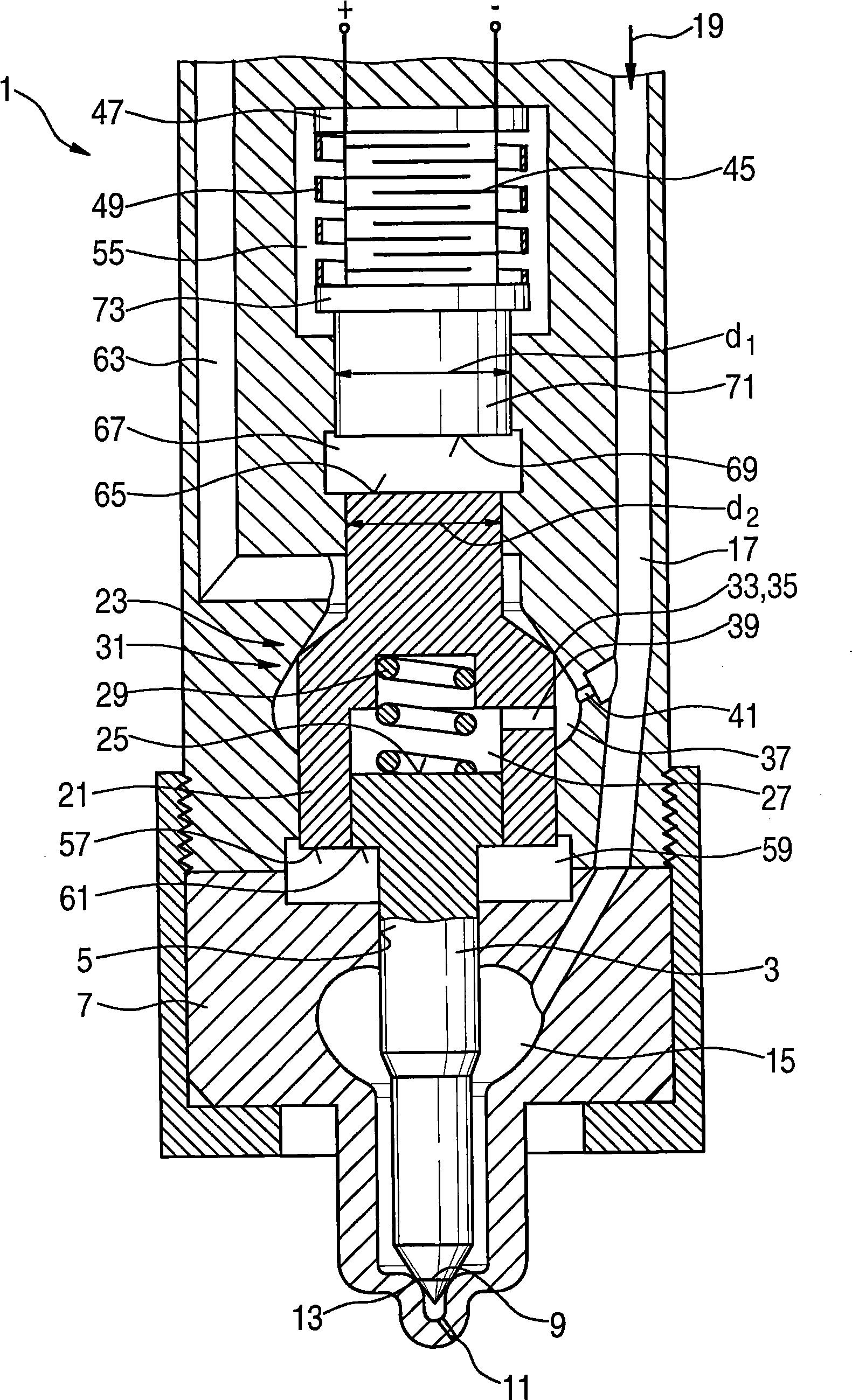
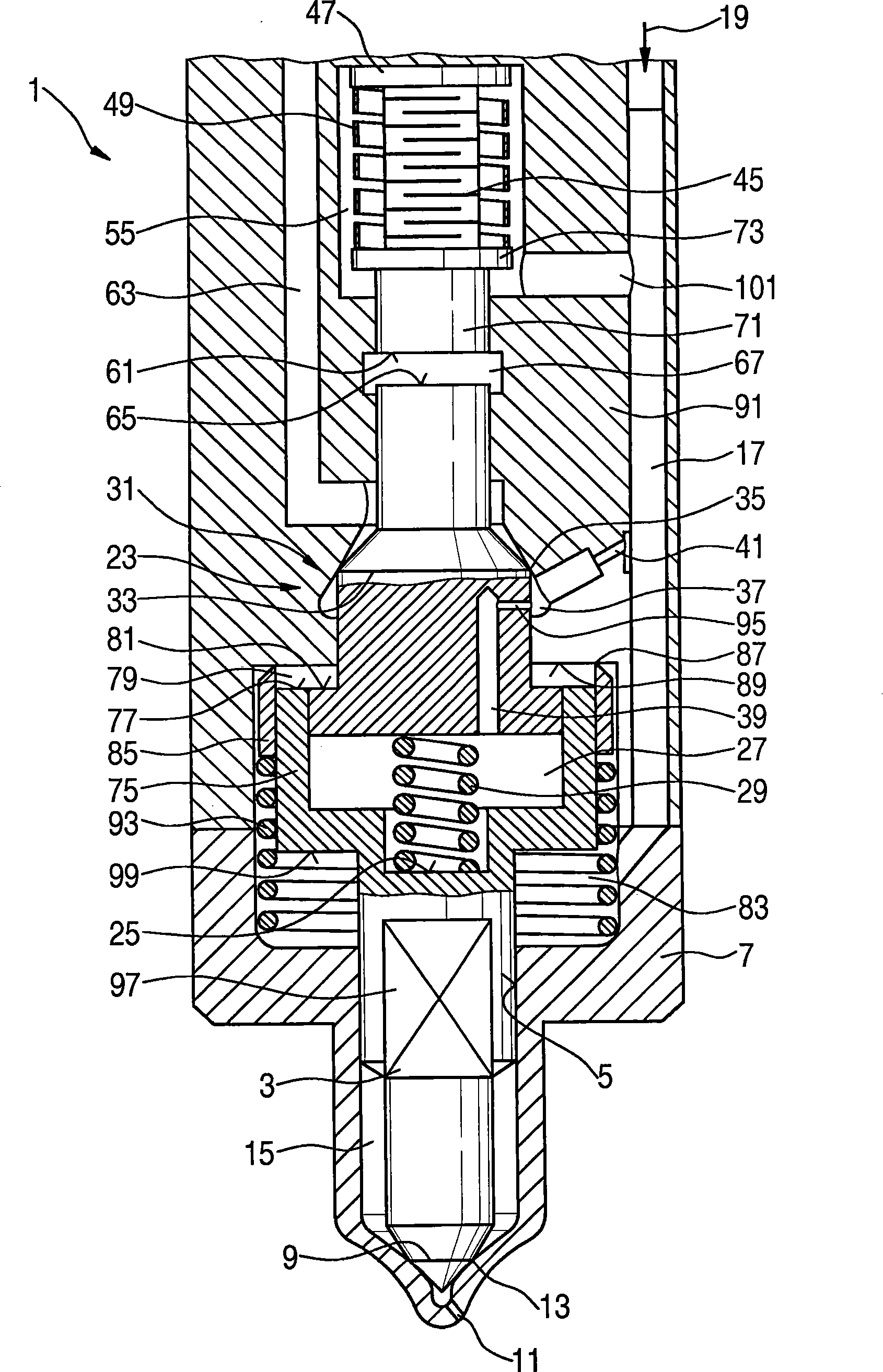
[0023] The fuel injector 1 includes an injection valve element 3 which is guided in a guide 5 in a lower housing part 7 . A sealing edge 9 is formed on the injection valve element 3 and rests in a seat 13 when the injection opening 11 is closed. In addition to the exemplary embodiment shown here in which fuel injector 1 has one injection opening 11 , more than one injection opening 11 can also be provided.

[0024] The injection valve element 3 is surrounded by a nozzle chamber 15 . The nozzle chamber 15 is connected to a fuel inlet 19 via an inlet channel 17 . The fuel inlet 19 is in turn connected to a common rail system high-pressure accumulator (not shown here).

[0025] On its end facing away from the injection opening 11 , the injection valve element 3 has a piston section which is guided in an annular section 21 of the control piston 23 . An end face 57 is formed on the annular section 21 , which acts as a pressure face on the control chamber 59 . A shoulder 61 is f...


PUM


Abstract

The invention relates to an injector for injecting fuel into a combustion chamber of an internal combustion engine, wherein the injector (1) is actuated by means of an actuator (45) and is connected to a fuel supply line (19) via which fuel is supplied under system pressure, and in which at least one injection opening (11) can be opened or closed off by an injection valve member (3), wherein the injection valve member (3) is activated by means of a control piston (23) via a control space (29) to which the control piston (23) and a piston section of the injection valve member (3) are exposed with respective pressure faces (57, 61). The control piston (23) is a valve piston of a control valve (31). The pressure face (57) of the control piston (23) and the pressure face (61) of the piston section of the injection valve member (3) are exposed to the control space (59) at the same side. The control piston (23) and the piston section of the injection valve member (3) also enclose a further control space (27) which is connected to a fuel return line (63) when the control valve (31) is open and to the fuel supply line (19) when the control valve (31) is closed.

Description

technical field [0001] The invention relates to an injector for injecting fuel into a combustion chamber of an internal combustion engine according to the preamble of claim 1 . Background technique [0002] Known from DE-A 10 2004 015 744 is a fuel injector for injecting fuel into the combustion chamber of an internal combustion engine, which has an injector housing with a fuel inlet, which is connected to the injector housing A central high-pressure source of fuel outside the body and connected to a pressure chamber inside the injector housing, depending on the position of the control valve, injects high-pressure fuel from the fuel inlet. The control valve is operated by a piezoelectric actuator. In order to achieve a sufficiently large lifting stroke of the control valve, a coupling chamber is formed between the control valve and the piezoelectric actuator. This coupling chamber serves as a hydraulic transducer acting on the valve piston of the control valve. [0003] A...

Claims


Application Information

Patent Timeline
Patent Type & Authority Applications(China)
IPC IPC(8): F02M47/02F02M51/06
CPCF02M47/027F02M51/0603F02M2200/704
Inventor F·伯金
Owner ROBERT BOSCH GMBH
Learn More