Expandable spinal implant

a spinal implant and expandable technology, applied in the field of expandable spinal implants, can solve the problems of increasing the distance between adjacent vertebrae and the expansion of the overall foot-print of the expandable spinal implant, and achieve the effect of uniform deploymen

Inactive Publication Date: 2018-03-15
41MEDICAL AG
View PDF2 Cites 1 Cited by
  • Summary
  • Abstract
  • Description
  • Claims
  • Application Information

AI Technical Summary

Benefits of technology

[0012]It is the object of the invention to create an expandable spinal implant that allows a uniform movement of any part of the implant, thus yielding a uniform deployment of the implant in the intervertebral space between adjacent vertebrae.

Problems solved by technology

Hence, expansion of the inventive expandable spinal implant only results in an expansion of the overall foot-print of the expandable spinal implant while the distance between the adjacent vertebrae is not increased.

Method used


Image

  • Expandable spinal implant
  • Expandable spinal implant
  • Expandable spinal implant

Examples


Embodiment Construction

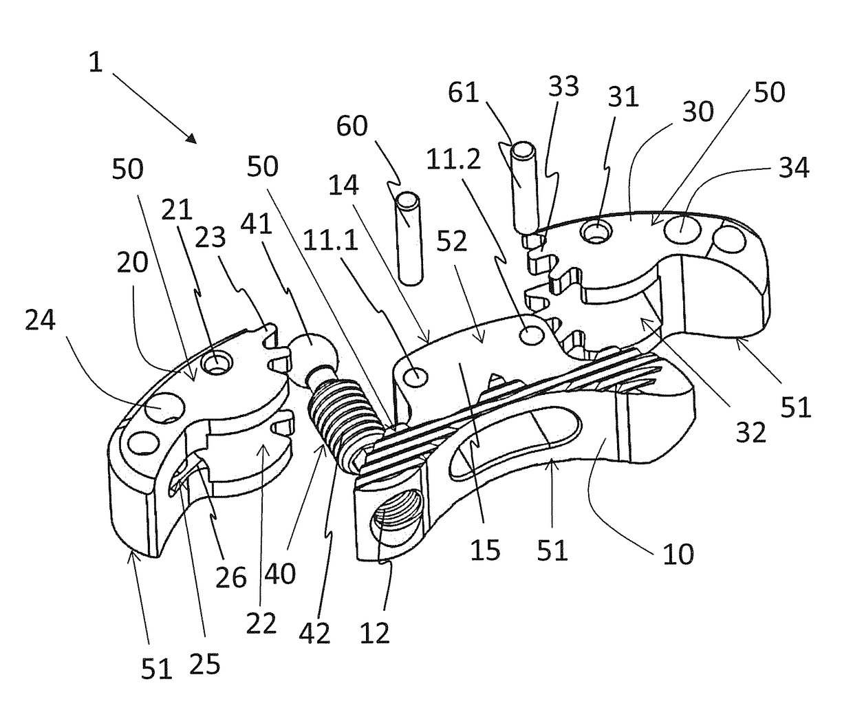
[0059]FIG. 1 shows a first embodiment of the expandable spinal implant 1 in an exploded view. The expandable spinal implant 1 comprises a first elongated implant member 20, a second elongated implant member 30, a central base portion 10, two hinge-pins 60, 61 and a dowel 40.

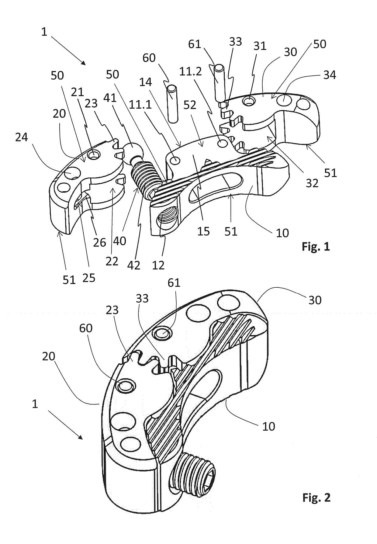
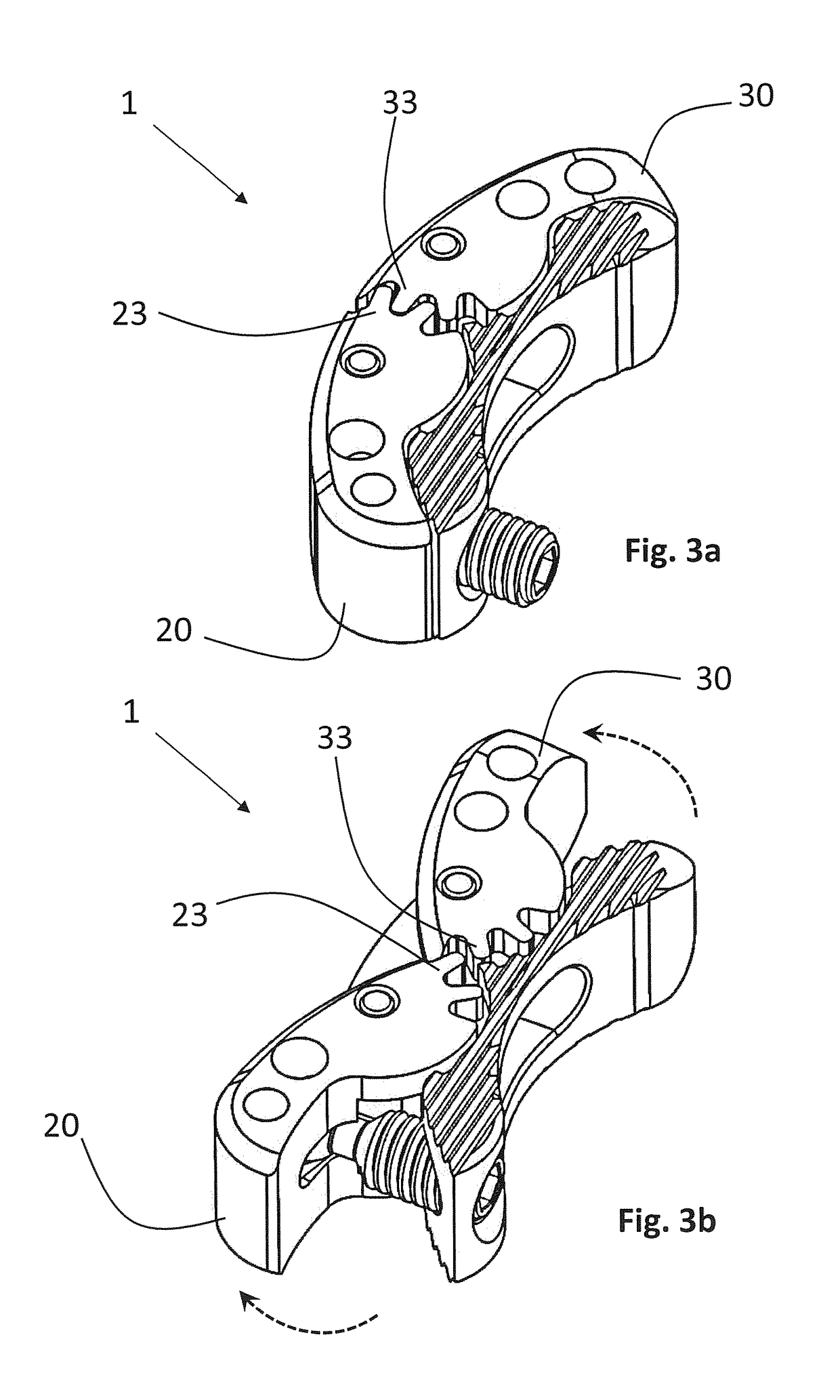
[0060]Each of the elongated implant members 20, 30 comprises an axis of rotation at a first end. Each axis of rotation is defined by a corresponding bore 21, 31 into which one of the two hinge-pins 60, 61 is inserted. Furthermore, the elongated implant members 20, 30 each comprise a recess 22, 32 extending through the elongated implant member 20, 30 and intersecting with the bores 21, 31 wherein each recess 22, 32 is substantially perpendicularly arranged in reference to the respective axis of rotation defined by each bore 21, 31. Said first ends of the elongated implant members 20, 30 are of a half cylindrical shape and comprise a set of gear teeth 23, 33, circumferentially arranged around the axis of rotation d...


PUM


Abstract

The present application relates to an expandable spinal implant (1) comprising two elongated implant members (20, 30). The implant members (20, 30) are rotatably coupled to a central base portion (10) and comprise a first end with an axis of rotation and circumferentially arranged gear teeth (23, 33). The gear teeth (23) of the first elongated implant member (20) is interlocked into said gear teeth (33) of the second elongated implant member (30).

Description

TECHNICAL FIELD[0001]The invention relates to an expandable spinal implant to be arranged between two adjacent vertebral bodies.BACKGROUND[0002]Low back pain is a common disease for example caused by herniated discs, compressed nerve roots, degenerative discs or joint disease.[0003]If a patient has this severe pain and does not respond to conservative treatment, spinal fusion is an option to eliminate the pain. Spinal fusion is a surgical technique, wherein two or more vertebrae are joined together. Spinal fusion interventions are also performed to correct back deformities.[0004]With inter-body fusion often an intervertebral spacer or device is placed between the involved vertebrae after removal of the intervertebral disc. The intervertebral device corrects the spine alignment and restores the disc height.[0005]Common intervertebral devices are made from titanium alloys or polyetheretherketone (PEEK). Often these devices comprise pockets that can be filled with bone graft material o...

Claims


Application Information

Patent Timeline
Patent Type & Authority Applications(United States)
IPC IPC(8): A61F2/44
CPCA61F2/4425A61F2/4455A61F2/4465A61F2002/30179A61F2002/30507A61F2002/30523A61F2002/3054A61F2002/30545A61F2002/3055A61F2002/30579A61F2002/30593A61F2002/30616A61F2310/00023A61F2002/30378A61F2002/30471A61F2/442A61F2002/4629A61F2/447A61F2002/30525A61F2/4611
Inventor OVERES, TOM
Owner 41MEDICAL AG
Why Eureka
Try Eureka