
Pressure tight large-scaled membrane structure

a large-scale, membrane technology, applied in the direction of transportation and packaging, lighter-than-air aircraft, weapons, etc., can solve the problems of difficult balloon weight reduction, difficult to continue flying, and the possibility of other methods of manufacturing pressure-tight balloons between 30 and 50 km high,

Inactive Publication Date: 2013-11-26
THE FUJIKURA PARACHUTE COMPANY +1
View PDF23 Cites 5 Cited by
  • Summary
  • Abstract
  • Description
  • Claims
  • Application Information

AI Technical Summary

Benefits of technology

The present invention aims to solve the problem of non-uniform deployment of gores in large-scale membrane structures. The technical effect of this invention is to provide a pressure tight large-scaled membrane structure that can uniformly deploy all gores.

Problems solved by technology

As a matter of fact, in the zero-pressure type balloon, if the ballasts loaded at the beginning are all consumed, it is impossible to continue the flying.
As a result, it is hard to reduce the weight of the balloon such that the high tensile strength is necessary in the membrane, the very thick membrane is necessary and the like.
The practical pressure tight balloon which can reach the upper stratosphere having the height between 30 and 50 km can not be manufactured by other methods than this.
In other words, although the small-sized lobed pumpkin type balloon can be easily achieved, the large-sized lobed pumpkin type balloon is hard to be achieved.
If the phenomenon mentioned above is generated in the expanding process of the rising balloon, there is generated a problem that it is impossible to obtain a performance which is sufficient as the pressure tight balloon.
As a result, a large tension is generated.
As mentioned above, since a stable final shape is not guaranteed, and the pressure resistance is not guaranteed with respect to the large-scaled lobed pumpkin type balloon having a large number of gores 103, there is a problem that it is hard to put the large-scaled super pressure balloon to practical use.
Accordingly, there is generated such a problem that the remaining gore 103 is fixed as it is without being deployed.
Therefore, it is impossible to deploy the balloon from the center portion thereof.

Method used


Image

  • Pressure tight large-scaled membrane structure
  • Pressure tight large-scaled membrane structure
  • Pressure tight large-scaled membrane structure

Examples


Embodiment Construction

[0059]A description will be given below of a best mode for carrying out the present invention.

[0060]In order to solve the problem mentioned above, the balloon may be structured as follows.

[0061]In other words, the balloon may be structured such that the balloon does not come to a final full expansion even at a time point when the gore of the balloon is deployed to a circumferential length defined by a length of the rope, and such a circumferential force that each of the gores forcibly and uniformly opens to the end.

[0062]Accordingly, first of all, a description will be given of the structure of the pressure tight balloon according to the present embodiment in which the deploying force mentioned above is generated, with reference to the accompanying drawings.

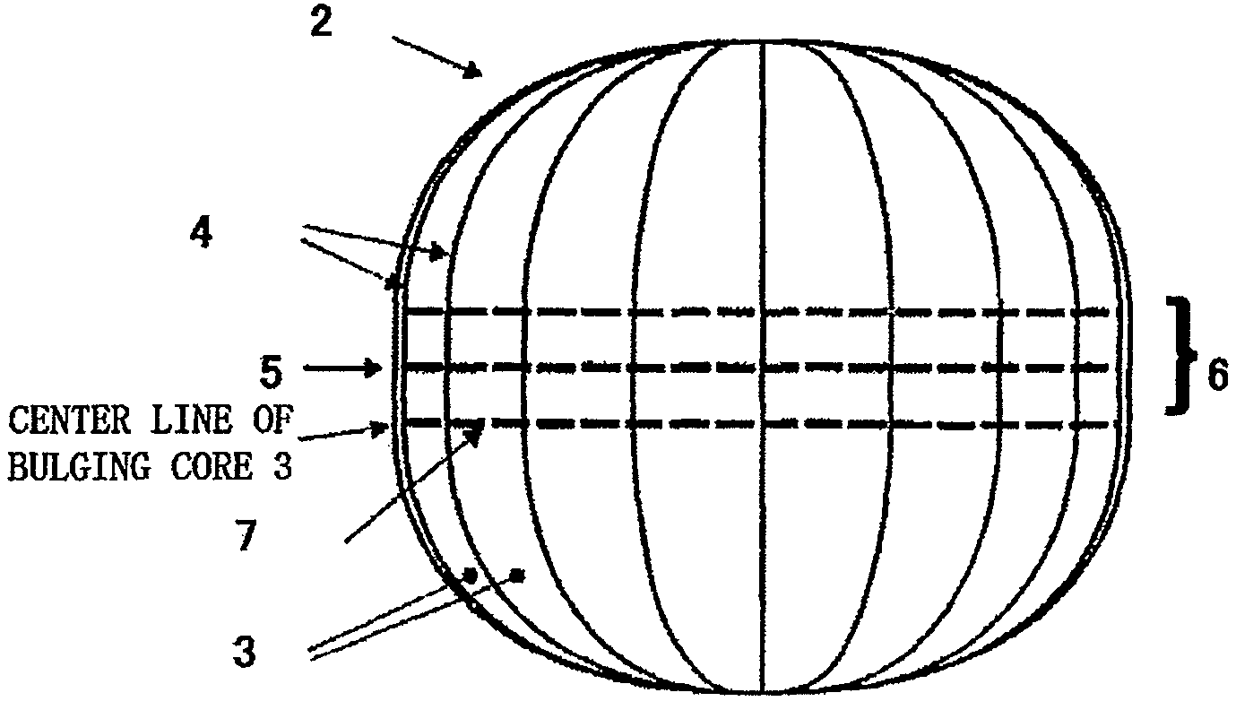
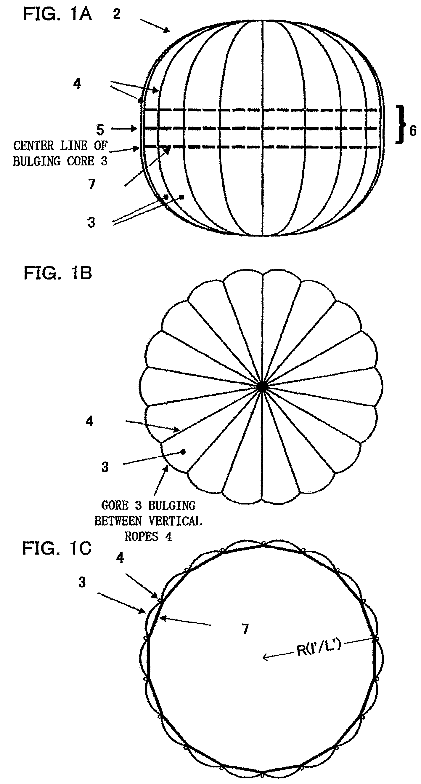
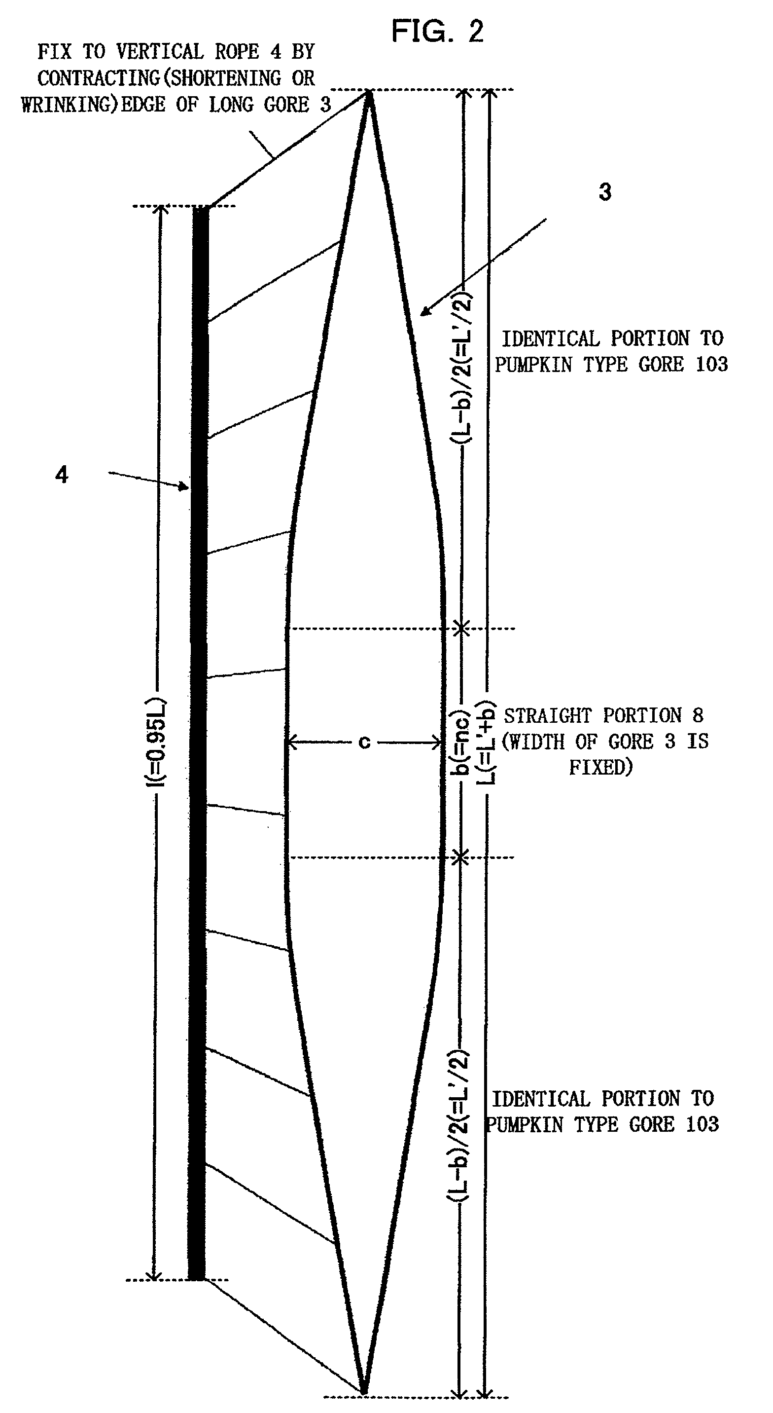
[0063]The pressure tight balloon according to the present embodiment shown in FIGS. 1A, 1B and 1C are structured on the basis of the pumpkin type balloon. In this case, the pumpkin type balloon is provided with a balloon shape wh...


PUM


Abstract

A pressure tight large-scaled membrane structure includes a bag body having a plurality of gores attached to each other along an attachment line, and a plurality of first ropes attached over a predetermined range of the bag body in such a manner as to be orthogonal to the attachment line of the gores, whereby a cylindrical shaped portion is formed. The cylindrical shaped portion has a substantially circular cross-sectional area that is a maximum substantially circular cross-section of the bag body and the plurality of first ropes each having approximately the same length as a circumference of the substantially circular-cross section having a maximum area with respect to the bag body.

Description

BACKGROUND OF THE INVENTION[0001]1. Field of the Invention[0002]The present invention relates to a pressure tight large-scaled membrane structure, and more particularly to a pressure tight large-scaled membrane structure which can uniformly deploy all gores.[0003]2. Description of the Related Art[0004]A scientific balloon taking a flight in an upper stratosphere having a height between 30 and 50 km is called as a zero-pressure type balloon, and generally loads a lot of ballasts. In the zero-pressure type balloon, the ballasts are dropped every night at a fixed rate with respect to a total floating weight. Generally, a temperature of a lifting gas (helium or hydrogen) within the balloon is lowered in the night, and a volume thereof becomes small accordingly, and buoyancy of the balloon is reduced. The reduction of the buoyancy of the balloon causes a reduction of a flying height of the balloon. With regard to this, it is possible to prevent the flying height of the balloon from being...

Claims


Application Information

Patent Timeline
Patent Type & Authority Patents(United States)
IPC IPC(8): B64B1/40B64B1/58
CPCB64B1/44B64B1/58B64B1/70
Inventor IZUTSU, NAOKIMATSUSHIMA, KIYOHO
Owner THE FUJIKURA PARACHUTE COMPANY
Learn More