Head-protection airbag device
a technology for airbags and head protection, which is applied in the direction of pedestrian/occupant safety arrangements, vehicular safety arrangments, vehicle components, etc., can solve the problem of not being able to deploy each portion of the airbag, and achieve the effect of reducing the time for completion and completing the deploymen
- Summary
- Abstract
- Description
- Claims
- Application Information
AI Technical Summary
Benefits of technology
Problems solved by technology
Method used
Image
Examples
first embodiment
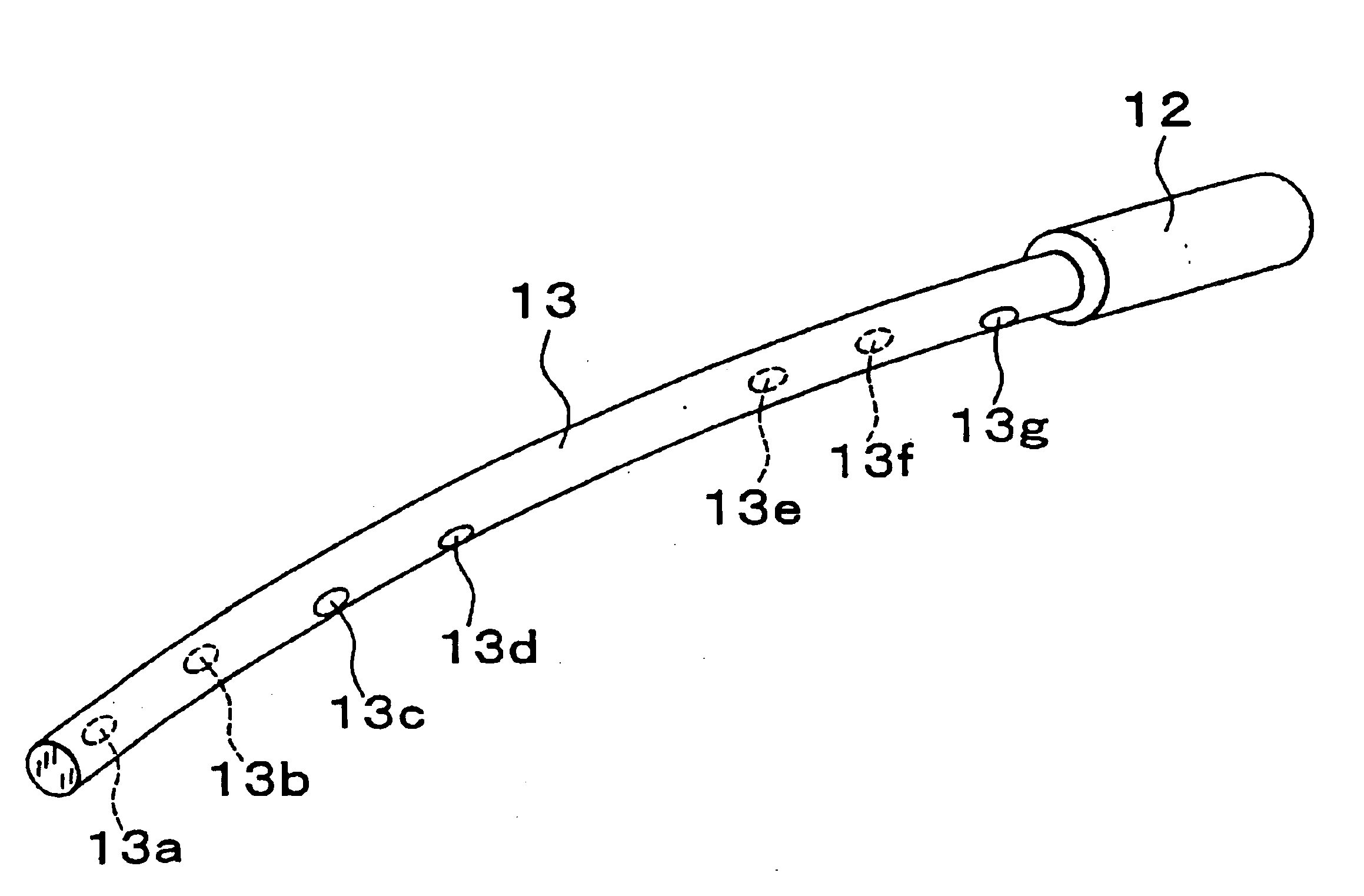
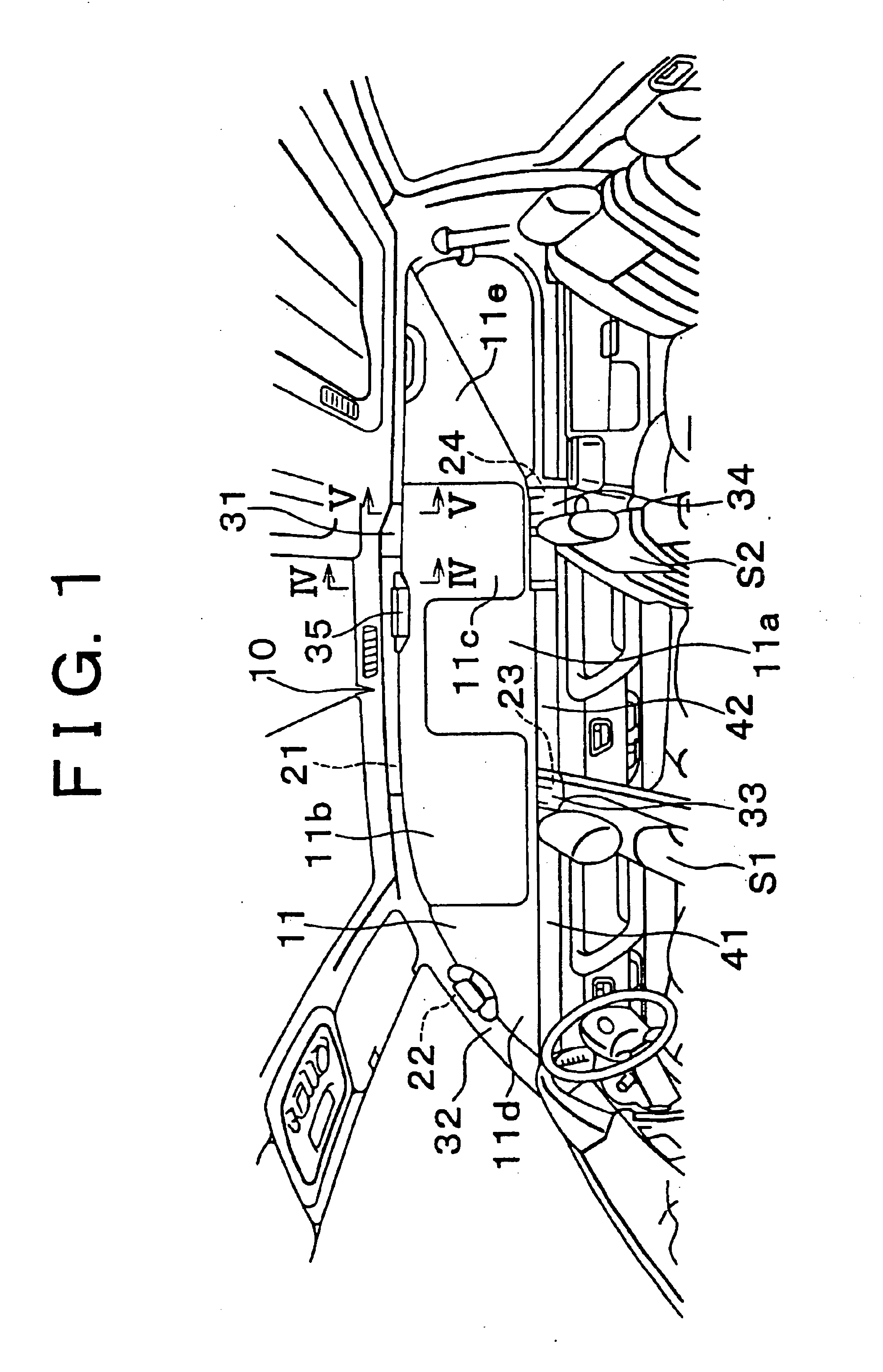
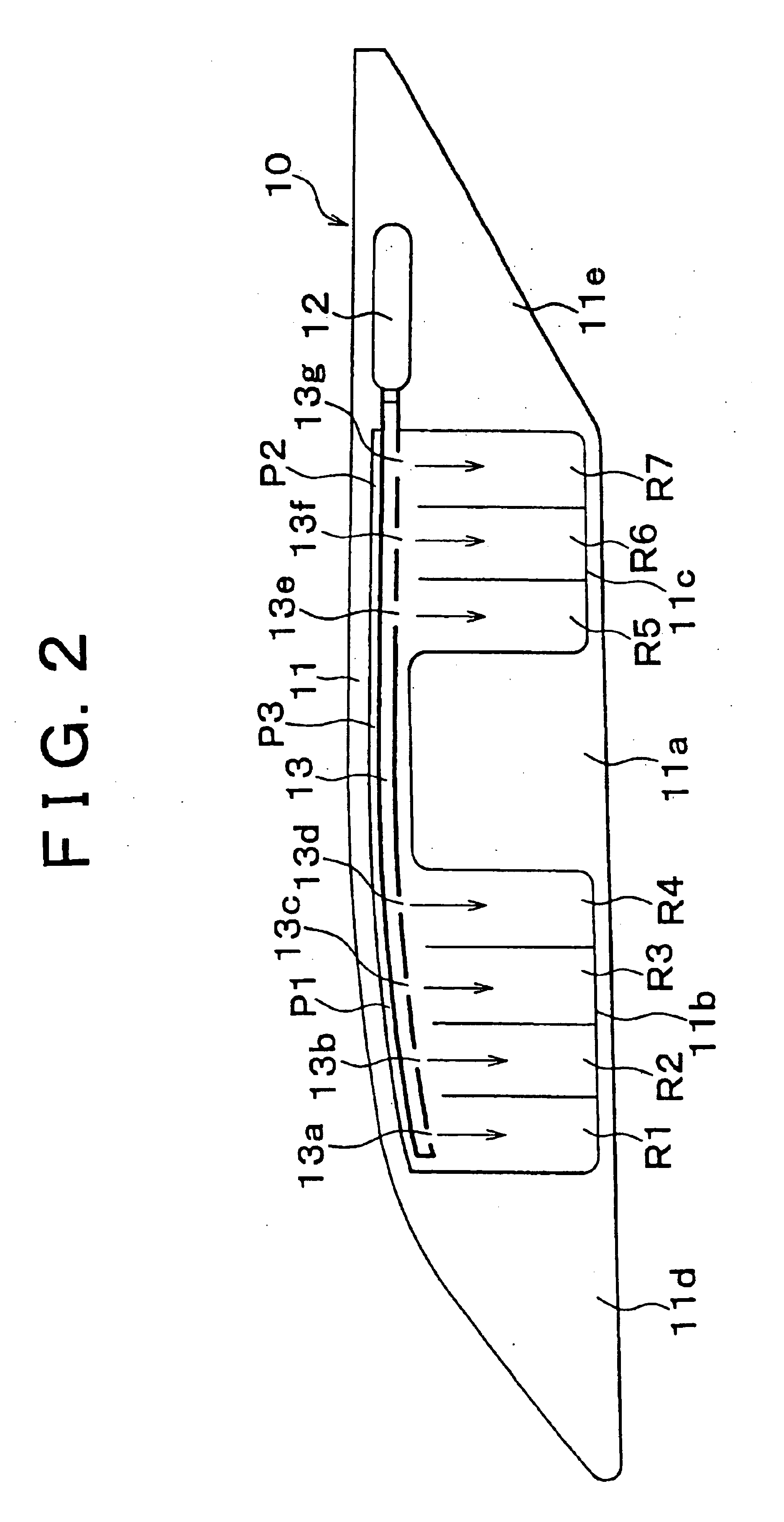
[0028]Hereinafter, the invention will be described in conjunction with the drawings. A head-protection airbag device 10 of the invention shown FIGS. 1 and 2 includes an airbag 11 inflated and deployed like a curtain along the sidewall of the vehicle compartment so as to protect the head of the occupant seated in a front seat S1 (the seat corresponding to a B pillar 23) and the head of the occupant seated in a rear front seat S2 (the seat corresponding to a C pillar 24), an inflator 12 serving as a gas supplier for supplying a gas to the airbag 11, and a gas distribution pipe 13 for distributing the gas supplied from the inflator 12 to each inflation chamber R1 to R7 of the airbag 11.
[0029]The airbag 11 is formed from foundation cloth (woven fabric) having an airtight coating thereon (the airtight coating may be omitted). As shown in FIGS. 1 and 2, the airbag 11 has a front-seat inflatable portion 11b and a rear-seat inflatable portion 11c with a central non-inflatable portion 11a in...
third embodiment
[0044]In the invention, a gas distribution pipe 53 is closed at its front end and is hermetically connected to the inflator 12 at its rear end. The gas distribution pipe 53 extends through the gas-introducing paths P1, P2 and P3 via the opening at the rear end of the rear gas-introducing path P2, and is hermetically sealed at this opening. The gas distribution pipe 53 includes gas outlets 53a, 53b corresponding to the front-seat inflatable portion 11b of the airbag 11, and gas outlets 53c, 53d corresponding to the rear-seat inflatable portion 11c.
[0045]The gas outlets 53a and 53b respectively correspond to the inflation chambers R1 and R4 which are disposed at the locations away from the head of the occupant in the front seat in the fore-and-aft direction of the vehicle. The gas outlets 53a and 53b are respectively opened toward the bottom of the inflation chambers R1 and R4, so that they can supply a gas to the respective inflation chambers R1 and R4. Note that part of the gas sup...
sixth embodiment
[0054]In each of the above embodiments, the inflator 12 may supply a gas to each inflation chamber R1 to R7 of the airbag 11 through the gas distribution pipe 53 extending through the gas-introducing paths P1 to P3 of the airbag 11. As in the invention shown in FIG. 10, however, the gas distribution pipe 53 may be eliminated so that the inflator 12 supplies a gas to each inflation chamber R1 to R7 of the airbag 11 through the gas-introducing paths P1 to P3 of the airbag 11.
[0055]Note that, in the sixth embodiment of FIG. 10, the inflation chambers R1 and R4 communicate with the gas-introducing path P1, and the inflation chambers R5 and R7 communicate with the gas-introducing path P2. Moreover, the inflation chambers R1 to R4 and the inflation chambers R5 to R7 each communicate with each other at their respective lower ends. In the sixth embodiment of FIG. 10, the inflator 12 is hermetically attached to the rear end of the rear gas-introducing path P2 in the airbag 11.
[0056]In the th...
PUM
 Abstract
Description
Claims
Application Information
 - R&D
- Intellectual Property
- Life Sciences
- Materials
- Tech Scout
- Unparalleled Data Quality
- Higher Quality Content
- 60% Fewer Hallucinations
Browse by: Latest US Patents, China's latest patents, Technical Efficacy Thesaurus, Application Domain, Technology Topic, Popular Technical Reports.
© 2025 PatSnap. All rights reserved.Legal|Privacy policy|Modern Slavery Act Transparency Statement|Sitemap|About US| Contact US: help@patsnap.com


