Connecting insert for a terminal assembly

a terminal assembly and insert technology, applied in the direction of permanent deformation connection, coupling base/case, electrical apparatus, etc., can solve the problems of problems such as oxidation at the and deformation of the electrical interface between the terminal and the wir

Active Publication Date: 2018-07-26
TYCO ELECTRONICS LOGISTICS AG (CH)
View PDF3 Cites 0 Cited by
  • Summary
  • Abstract
  • Description
  • Claims
  • Application Information

AI Technical Summary

Problems solved by technology

However, problems with oxidation may occur on the wire and / or the terminal.
For example, problems with oxidation may occur at the interface between a terminal and a wire in the presence of water.
However, the electrical interface between the terminal and the wire may be degraded if oxidation is present.
However, assembly of the terminal assemblies using the perforated inserts is difficult.
The perforated insert does not remain positioned on the end of the wire and may shift relative to the wire as the wire and the insert are inserted into the wire barrel of the terminal, which may lead to the wire being only partially loaded into the terminal and an ineffective crimp.

Method used


Image

  • Connecting insert for a terminal assembly
  • Connecting insert for a terminal assembly
  • Connecting insert for a terminal assembly

Examples


Embodiment Construction

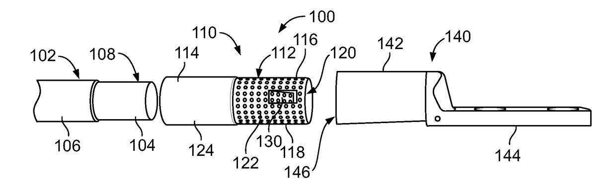
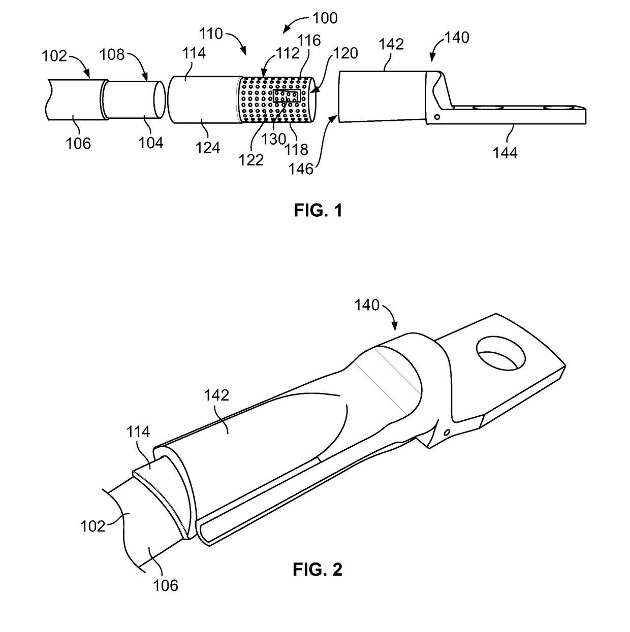
[0016]FIG. 1 is an exploded view of a terminal assembly 100 in accordance with an exemplary embodiment. The terminal assembly 100 includes a wire 102, a shuttle assembly 110 configured to be coupled to an end of the wire 102, and a terminal 140 configured to be terminated to the shuttle assembly 110 and the wire 102. The wire 102 includes an internal conductor 104 that is covered by an insulating cover 106. The conductor 104 may be formed of a conductive metal, such as copper, aluminum, or the like. The conductor 104 may be a solid core conductor or a stranded wire. The insulating cover 106 is formed of an insulating material, such as rubber, plastic, or the like. The insulating cover 106 may form a jacket of the wire 102. The wire 102 may include other layers such as a wire braid, an outer jacket, and the like. A portion of the insulating cover 106 is stripped in order to expose an end 108 of the conductor 104. In an exemplary embodiment, the shuttle assembly 110 and the terminal 1...


PUM


Abstract

A terminal assembly includes a terminal having a wire barrel and a mating segment configured to be mated to a mating component. The terminal assembly includes a shuttle assembly configured to be coupled to an end of a wire. The shuttle assembly includes a connecting insert defining a wire chamber configured to receive an exposed conductor of the wire. The connecting insert has a retention tab extending into the wire chamber. The retention tab is configured to interfere with and retain the wire in the wire chamber. The connecting insert is received in the wire barrel of the terminal and the connecting insert is configured to be crimped between the wire barrel of the terminal and the exposed conductor of the wire when the wire barrel is crimped around the connecting insert and the wire.

Description

BACKGROUND OF THE DISCLOSURE[0001]Embodiments of the present disclosure generally relate to connecting inserts for terminal assemblies.[0002]Terminal assemblies are used to provide power and / or data signals between various components. A typical wire assembly includes an insulating cover that surrounds portions of a conductive wire. A distal end of the insulating cover may be stripped in order to expose a portion of the conductive wire so that the exposed portion of the conductive wire may contact conductive portions of a terminal.[0003]In order to electrically and mechanically connect the wire to the terminal, portions of the wire and the terminal may be crimped together. Typically, the terminal is crimped directly to the wire. However, problems with oxidation may occur on the wire and / or the terminal. For example, problems with oxidation may occur at the interface between a terminal and a wire in the presence of water. Some known terminal assemblies provide a seal that is crimped a...

Claims


Application Information

Patent Timeline
Patent Type & Authority Applications(United States)
IPC IPC(8): H01R4/20
CPCH01R4/203H01R13/52H01R4/20H01R4/2495
Inventor MOORE, RICHARD FRANKMULFINGER, ROBERT NEILLUCENTE, RICHARD VINCENTTHACKSTON, KEVIN MICHAELKLINGER, BRIAN TODDRUFFINI, NICHOLAS PAUL
Owner TYCO ELECTRONICS LOGISTICS AG (CH)
Why Eureka
Try Eureka