Liquid discharging apparatus

a technology of liquid discharging apparatus and discharging ink, which is applied in the direction of printing, spacing mechanisms, inking apparatus, etc., can solve the problems of discharging ink, reducing printing accuracy or printing stability, and occurrence of overshoot or undershoot of drive signals

Active Publication Date: 2018-09-27
SEIKO EPSON CORP
View PDF4 Cites 19 Cited by
  • Summary
  • Abstract
  • Description
  • Claims
  • Application Information

AI Technical Summary

Benefits of technology

[0028]The occurrence of overshoot or undershoot is likely to increase since a change in the voltage of the drive signal becomes steeper as a frequency at which a liquid is discharged becomes higher (as a speed at which printing is performed increases). In the liquid dischargi

Problems solved by technology

In a case where a control signal and a drive signal are transmitted to a print head via a flexible cable (signal line), there is a possibility that the occurrence of overshoot or undershoot of the drive signal increases due to an effect of inductance of wiring for transmitting the drive signal and the print head breaks down by an overvoltage that exceeds a withstand voltage being instantaneously applied to a circuit mounted on the print head or to a driving element.
In addition, printing accuracy or printing stability declines, or malfunction such as false discharging of an ink occurs as the voltage of a drive signal drops significantly due to an effect of impedance of the wiring for transmitting a drive signal.
Therefore, a control signal with a low voltage is likely to receive an effect of a drive signal with a high voltage, and malfunction such as false discharging occurs.
As a consequence, an expensive motor is necessary and i

Method used


Image

  • Liquid discharging apparatus
  • Liquid discharging apparatus
  • Liquid discharging apparatus

Examples


modification example

6. Modification Example

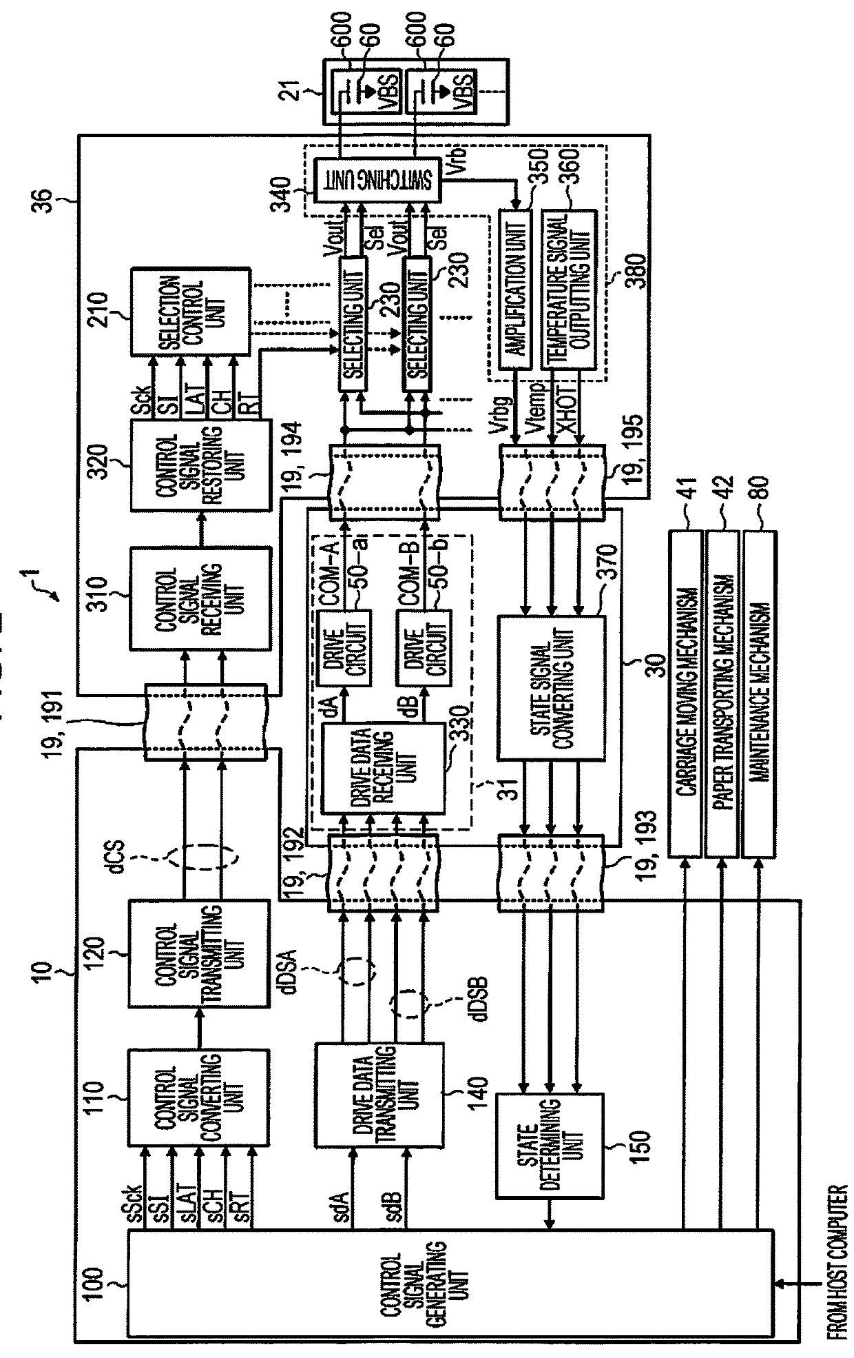
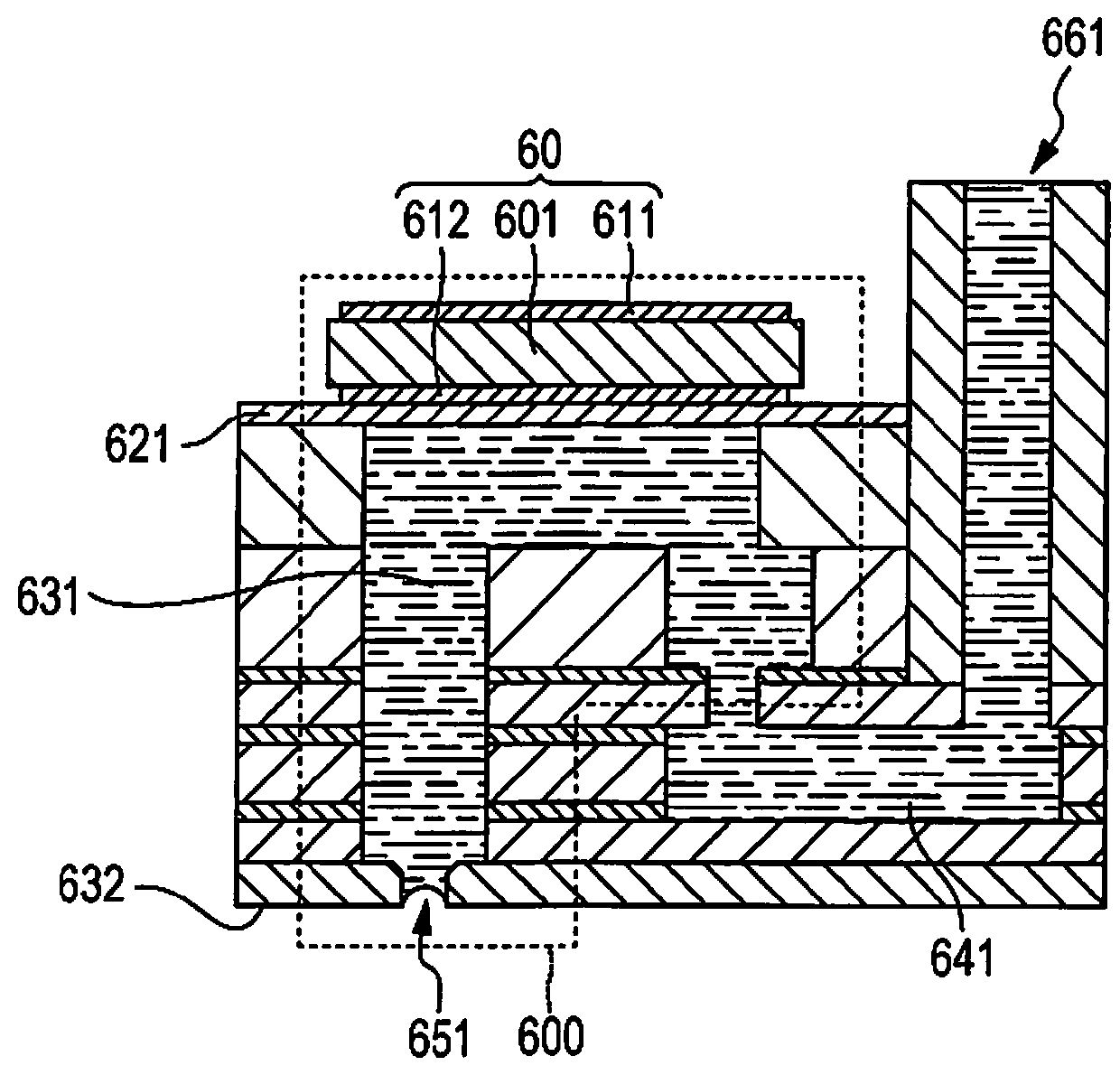
[0266]Although a piezoelectric liquid discharging apparatus in which a drive circuit drives a piezoelectric element (capacitive load) as a driving element is given as an example in the embodiment described above, the invention is also applicable to a liquid discharging apparatus in which a drive circuit drives a driving element other than a capacitive load. As an example of such a liquid discharging apparatus, a thermal (bubble type) liquid discharging apparatus, in which a drive circuit drives a heater element (for example, a resistance) as a driving element and a liquid is discharged using bubbles generated by the heater element being heated, can be given.

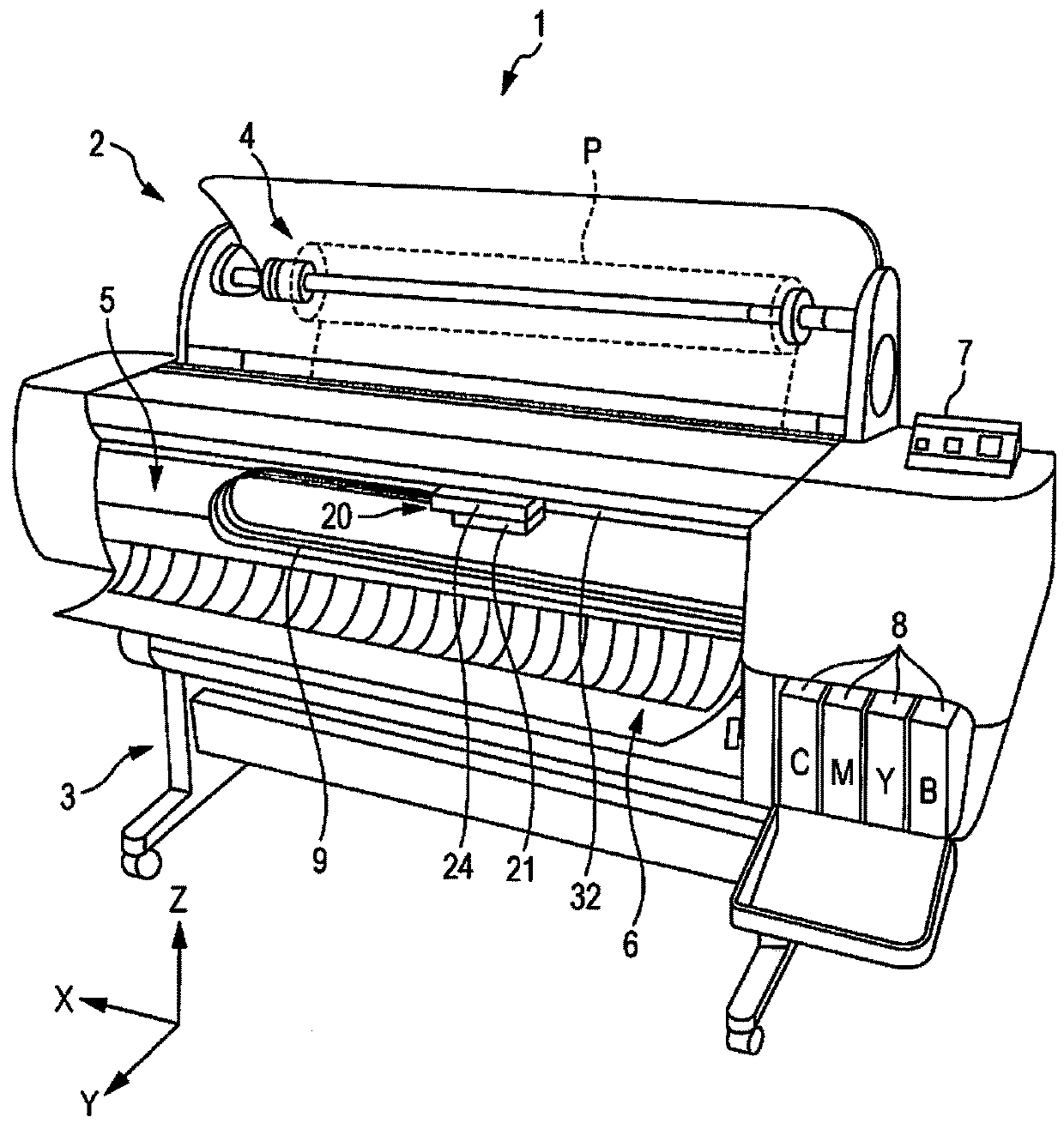
[0267]Although a printing apparatus such as a printer is given as an example of a liquid discharging apparatus in the embodiment described above, the invention may be a liquid discharging apparatus that discharges a liquid onto a medium having a size of A3 or larger, and is also applicable to liquid dischar...


PUM


Abstract

A liquid discharging apparatus includes a print head that discharges a liquid, a carriage that is mounted on the print head, a control signal generation circuit, a drive signal generation circuit, a first cable through which a drive signal generation control signal is transmitted to the drive signal generation circuit, a second cable through which a drive signal is transmitted to the print head, a control circuit substrate on which the control signal generation circuit is provided, and a drive circuit substrate on which the drive signal generation circuit is provided. The shortest distance between the control circuit substrate and the carriage is longer than the shortest distance between the drive circuit substrate and the carriage. The drive circuit substrate is provided at a position where a region in which the carriage moves and at least a part of the drive circuit substrate overlap each other.

Description

BACKGROUND1. Technical Field[0001]The present invention relates to a liquid discharging apparatus.2. Related Art[0002]An apparatus using a piezoelectric element is known as a liquid discharging apparatus such as an ink jet printer that discharges inks and prints an image or characters. The piezoelectric element is provided so as to correspond to each of a plurality of nozzles in a head (print head), and each of the nozzles is driven in accordance with a drive signal. As a consequence, a predetermined amount of ink (liquid) is discharged at a predetermined timing from the nozzles, and thereby dots are formed. Since the piezoelectric element is a capacitive load like a capacitor from an electrical perspective, it is necessary to supply a sufficient amount of current in order to operate the piezoelectric element of each nozzle. For this reason, a configuration where a drive circuit supplies a drive signal amplified by an amplification circuit and the piezoelectric element is driven is ...

Claims


Application Information

Patent Timeline
IPC IPC(8): B41J2/045B41J2/15B41J2/14B41J11/00
CPCB41J2/04541B41J2/15B41J2/04508B41J2/04581B41J2202/13B41J11/001B41J2/1433B41J2002/14491B41J2/14201B41J2/01B41J2/045B41J2/04588B41J2/04593B41J19/005
Inventor ITO, SUKEHIROHAYAKAWA, NAOTOHIRAMATSU, KAZUNORI
Owner SEIKO EPSON CORP
Why Eureka
Try Eureka