
Optical system, method, and applications

a technology of optical system and optical beam, applied in the field of optical system, can solve the problems of poor color mixing and inability to deliver very uniform beam of light, and achieve the effect of high punch

Inactive Publication Date: 2018-11-01
SIGNIFY HLDG BV
View PDF2 Cites 9 Cited by
  • Summary
  • Abstract
  • Description
  • Claims
  • Application Information

AI Technical Summary

Benefits of technology

The patent text describes a new optical system that can improve the tightness, brightness, and uniformity of a beam of light. This system can also enhance color mixing at the far field, resulting in a more efficient and effective optical system. Compared to conventional systems, the new system achieves a higher punch and a tighter beam with a maximum angle of approximately 5 degrees. The efficiency of the system is 90% or higher, which means that most of the energy is delivered to the desired area. This new system can provide significantly better performance and quality for applications that require precise and bright lighting, such as medical imaging or laser displays.

Problems solved by technology

A related problem with such conventional optical systems is that they do not deliver a very uniform beam of light.
Further, when such conventional optical systems are packed together in a cluster or otherwise associated with other such optical systems, color mixing can be very poor.

Method used


Image

  • Optical system, method, and applications
  • Optical system, method, and applications
  • Optical system, method, and applications

Examples


Embodiment Construction

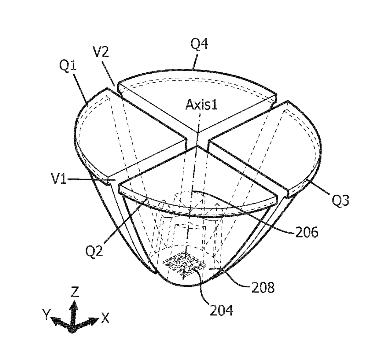
[0054]The present disclosure describes various embodiments of an improved optical system. More generally, Applicant has recognized and appreciated that it would be beneficial to provide an optical system that includes an array of different colored LEDs, each of which being disposed at a separate focal point within an optic formed of a TIR light-directing housing, and grouping a certain number of such optics together in a particular manner for the purposes of providing a tighter, brighter and more uniform beam of light and better color mixing in the far field as compared to the conventional optical systems.

[0055]In one arrangement, a substantially improved, tighter, brighter and more uniform beam of light can be obtained by providing the array of different colored LEDs, each of which being disposed at a separate focal point within an optic formed of a TIR light-directing housing, as opposed to the conventional optical systems which utilize a single LED disposed within an optic. In an...


PUM


Abstract

An optical system (200, 300, 400), including: at least one 2×2 LED array forming a node (204) consisting of four different color LEDs: LED1(G), LED2(R), LED3 (B), LED4(W) and at least one respective TIR light-directing housing forming an optic (202) having a base end (208) and a light-emitting end (210), in which the node is disposed in the base end. The optic is characterized by a shape having four different focal points (F1, F2, F3, F4), and each of the LED1, LED2, LED3, LED4 is disposed at a respective one of the focal points.

Description

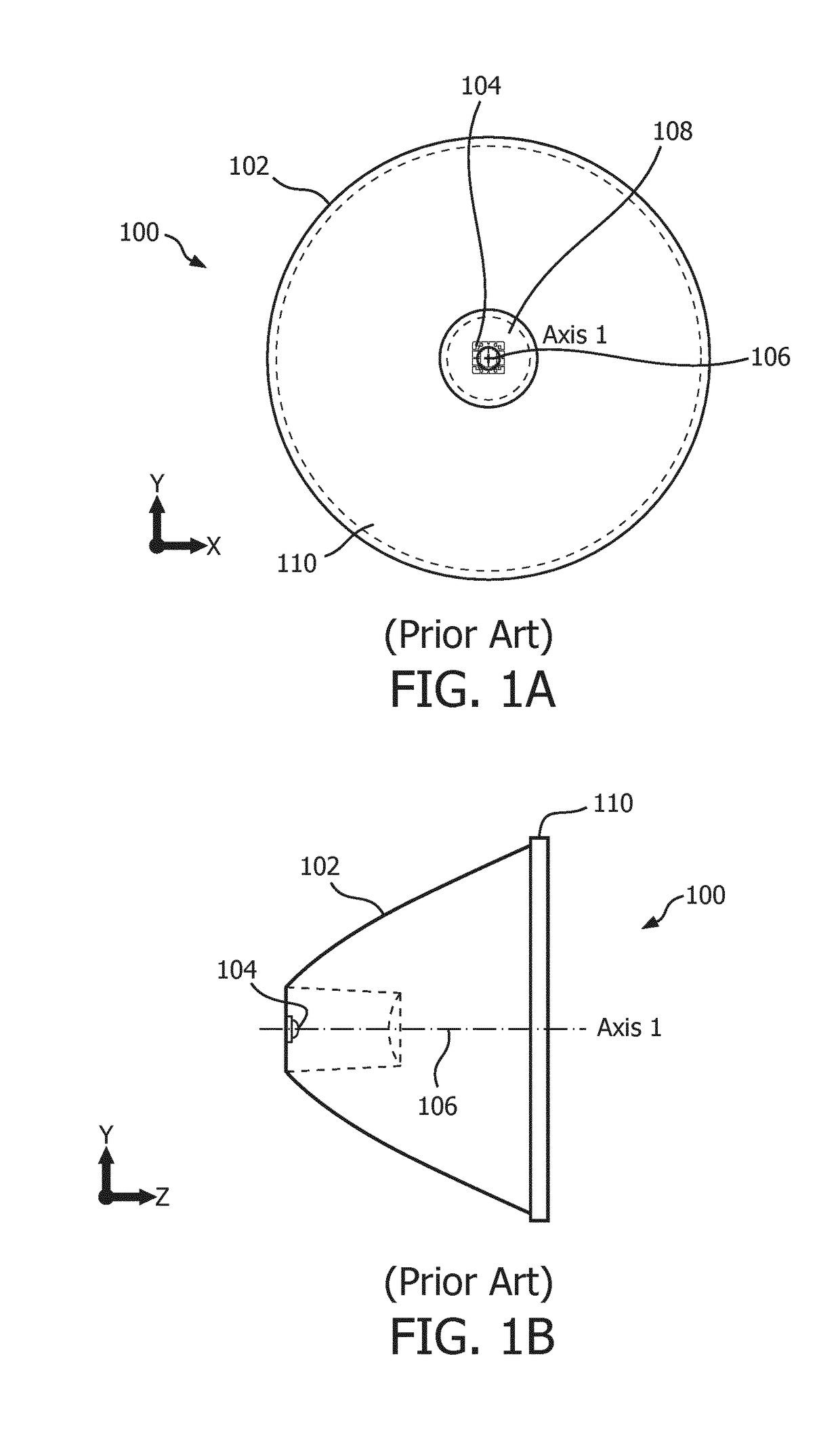
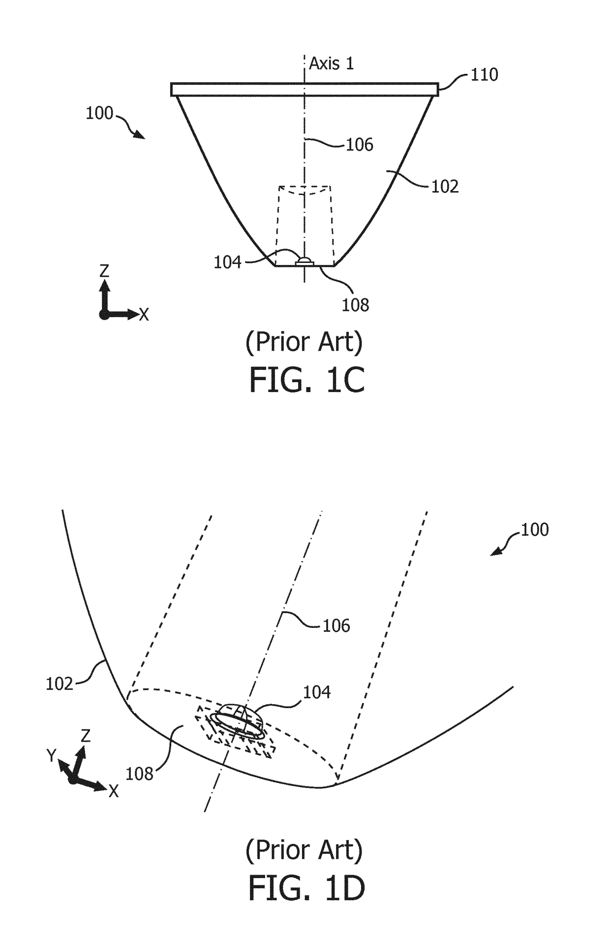
FIELD OF THE INVENTION[0001]The present disclosure is directed generally to an optical system, and more particularly, to an optical system including an array of different colored LEDs, each of which being disposed at a separate focal point within an optic formed of a total internal reflection (“TIR”) light-directing housing with a TIR profile and to a grouping of a certain number of such optics together in a particular manner.BACKGROUND[0002]Optical systems including a single LED disposed within an optic with a TIR profile are known. The single LED is positioned at the base of the optic so that the central axis of the optic extends through the center of the single LED, which is known as the single focal point of the optic with a coordinate of 0, 0, 0 in the x, y, and z planes, respectively. A related problem with such conventional optical systems is that they do not deliver a very uniform beam of light. Further, when such conventional optical systems are packed together in a cluster...

Claims


Application Information

Patent Timeline
Patent Type & Authority Applications(United States)
IPC IPC(8): F21V7/00F21V7/07
CPCF21V7/0091F21V7/07F21V7/0083F21V7/0066F21Y2113/17F21Y2115/10F21V5/007F21V5/04F21Y2113/13G02B19/0028G02B19/0066
Inventor LACROIX, LUC GUY LOUIS
Owner SIGNIFY HLDG BV
Learn More