
Operation state classification apparatus

Active Publication Date: 2018-11-01
MITSUBISHI ELECTRIC CORP
View PDF11 Cites 6 Cited by
  • Summary
  • Abstract
  • Description
  • Claims
  • Application Information

AI Technical Summary

Benefits of technology

The present invention provides an apparatus for classifying the operation states of a machine using a variety of sensors and physical quantities. This allows for effective failure detection and improved performance monitoring.

Problems solved by technology

In such a case, in the above control technique, when a measurement value of a specific sensor item exceeds the threshold value, it is very difficult to determine whether the exceeding is due to failure (abnormality) of the device or due to change of the operation state.
Therefore, there is a problem that detection accuracy of failures cannot be improved.
Meanwhile, if the number of sensor items used for the classification of operation states is increased, the number of classifications becomes excessive, and as a result, the same operation state does not occur and failure detection cannot be performed.

Method used


Image

  • Operation state classification apparatus
  • Operation state classification apparatus
  • Operation state classification apparatus

Examples


first embodiment

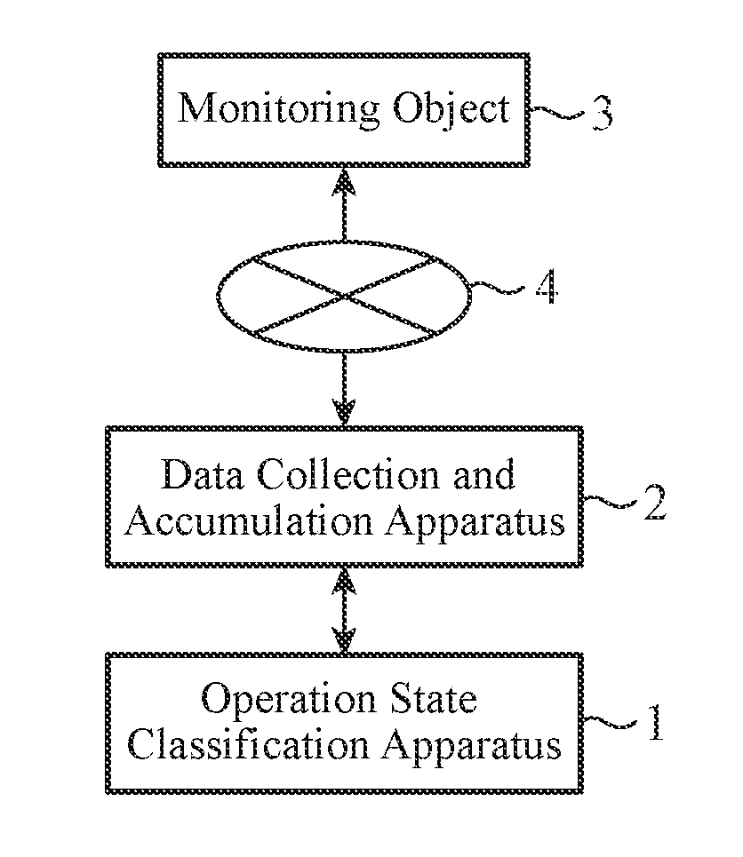
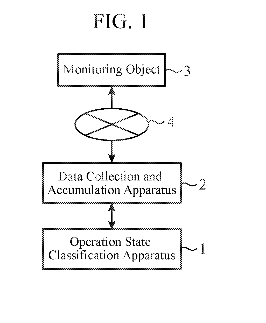
[0034]FIG. 1 is a configuration diagram of a sensor data classification system for causing an operation state classification apparatus 1 of a first embodiment of the present invention to classify sensor data collected from a monitoring object in a facility in accordance with an operation state.

[0035]As illustrated in FIG. 1, the sensor data classification system includes a monitoring object 3, a data collection and accumulation apparatus 2, and an operation state classification apparatus 1.

[0036]The monitoring object 3 is, for example, a device such as an air conditioner, an elevator, or a plant apparatus. The monitoring object 3 may be configured from one or more connected devices such as all air conditioning units in a building.

[0037]The monitoring object 3 and the data collection and accumulation apparatus 2 are connected by a sensor network 4, and the data collection and accumulation apparatus 2 continuously or intermittently collects and accumulates an aggregation of measuremen...

second embodiment

[0199]In the first embodiment, the operation state classification unit 14 calculates minimal points of the probability density function and divides the physical quantities, with respect to the physical quantity for failure determination calculated by the physical quantity for failure determination calculating unit 11, labels the physical quantity from division corresponding to smaller physical quantity, and generates the classification for each operation state, using the principal component, using the labels as training data.

[0200]In the second embodiment, an embodiment in which an operation state classification unit 14 estimates probability density distribution of principal components of a plurality of sensor data, divides the probability density distribution, and assigns an operation state number, thereby generating classification of the sensor data for each operation state, will be described.

[0201]FIG. 19 is a configuration diagram of an operation state classification apparatus 1...


PUM


Abstract

A principal component calculating unit (13) for calculating a principal component of a plurality of sensor data collected from a device, and a physical quantity for failure determination calculating unit (11) for calculating a physical quantity to be used for failure determination on the basis of the plurality of sensor data are provided. Further, an operation state classification unit (14) for generating classification, for each operation state, of the sensor data collected from the device, using the principal component calculated by the principal component calculating unit (13) and the physical quantity calculated by the physical quantity for failure determination calculating unit (11) is provided.

Description

TECHNICAL FIELD[0001]The present invention relates to an operation state classification apparatus that generates classification, for each operation state, of sensor data acquired from sensors installed in a control device in a control system of an elevator, a plant apparatus, an air conditioner, or the like.BACKGROUND ART[0002]In a device such as an elevator, a plant apparatus, or an air conditioner, a control technique to detect failure by comparing a measurement value acquired by a sensor installed in the device with a threshold value predetermined for each sensor item is known.[0003]However, some of various devices have variety of operation states depending on an installation environment, a model of the device, or a use state. In such a case, in the above control technique, when a measurement value of a specific sensor item exceeds the threshold value, it is very difficult to determine whether the exceeding is due to failure (abnormality) of the device or due to change of the ope...

Claims


Application Information

Patent Timeline
IPC IPC(8): G06K9/62G05B23/02
CPCG06K9/6247G05B23/0221G05B23/024G05B23/0254G06K9/6267G06F18/2135G06F18/24
Inventor KURIYAMA, TOSHIYUKIHIRAI, NORIOIMAMURA, MAKOTOHIRATA, TAKAHISANAKAMURA, TAKAAKI
Owner MITSUBISHI ELECTRIC CORP
Features
  • Generate Ideas
  • Intellectual Property
  • Life Sciences
  • Materials
  • Tech Scout
  • Unparalleled Data Quality
  • Higher Quality Content
  • 60% Fewer Hallucinations
Learn More