A trap

a trap and trap technology, applied in the field of traps, can solve the problems of requiring a regular maintenance program

Inactive Publication Date: 2018-11-08
REDMAYNE JOHN MICHAEL
View PDF14 Cites 7 Cited by
  • Summary
  • Abstract
  • Description
  • Claims
  • Application Information

AI Technical Summary

Benefits of technology

[0033]Preferably during the reset of the kill mechanism a ratchet mechanism is used to prevent an actuation or a release of the kill mechanism if the kill mechanism has not been reset to an armed position sufficient to effect a humane kill of the target creature.
[0034]Alternatively, a self-locking worm gear is used to hold the kill mechanism in a partially reset position if the device's gas and / or electricity is exhausted before the reset of the kill mechanism is completed and further wherein the device is configured to prevent an actuation or a release of the kill mechanism if the kill mechanism has not been reset to an armed position sufficient to effect a humane kill of the target creature.

Problems solved by technology

However, many traps typically require a regular program of maintenance by a worker.

Method used


Image

  • A trap
  • A trap
  • A trap

Examples


Embodiment Construction

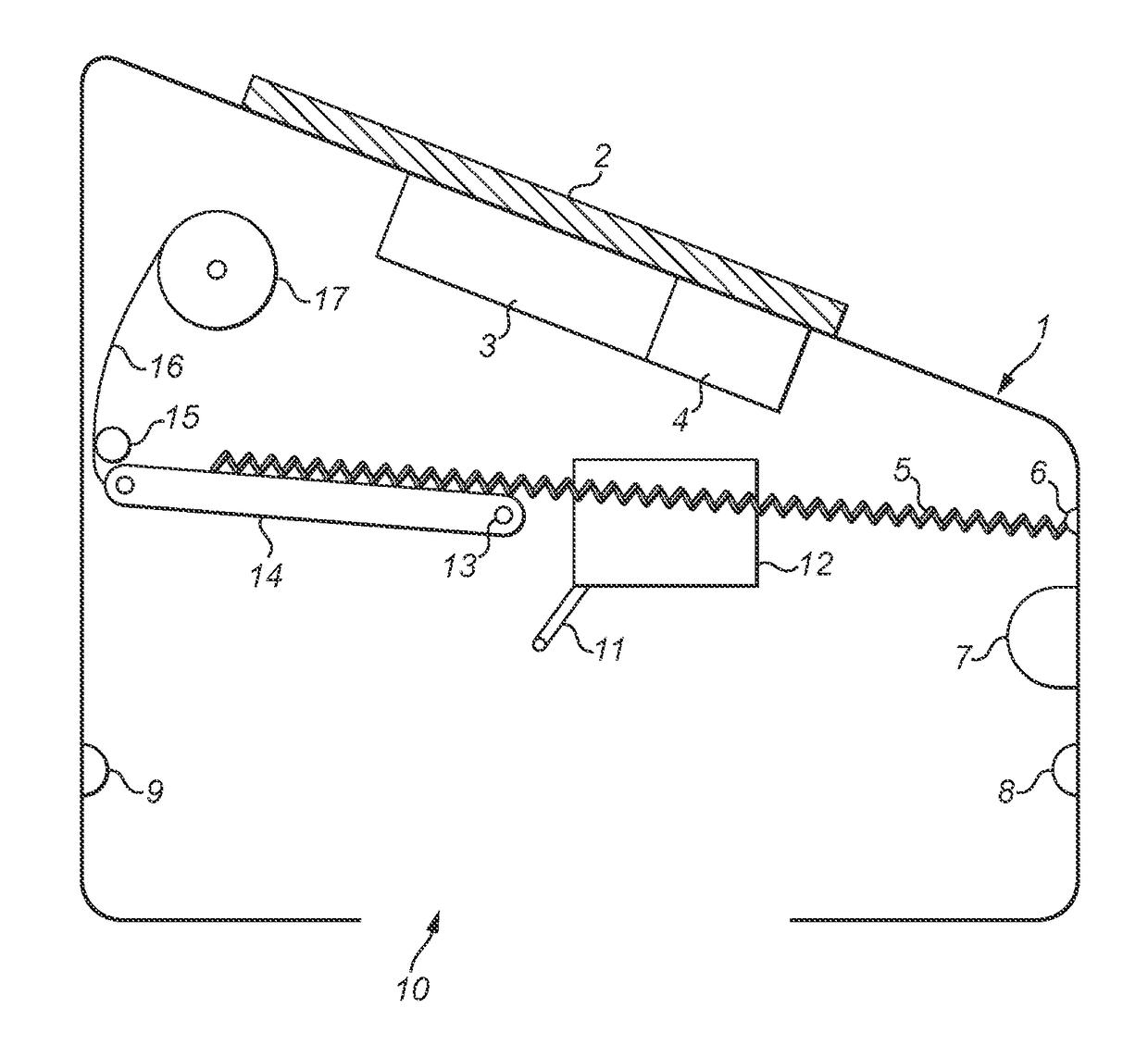
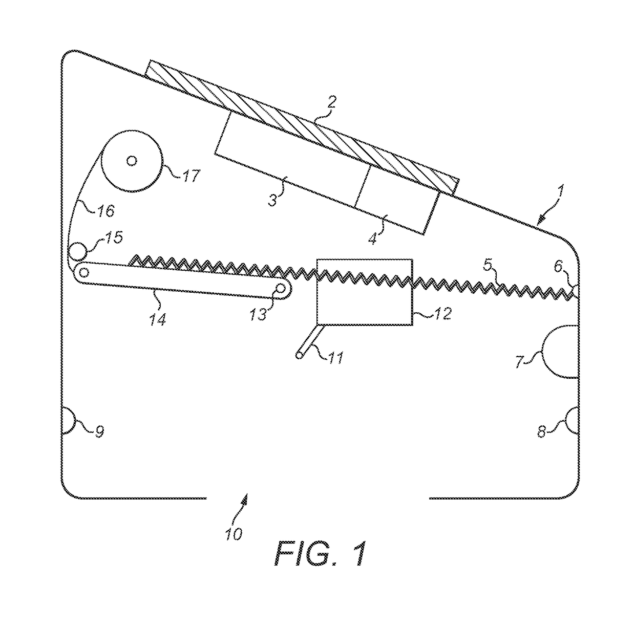
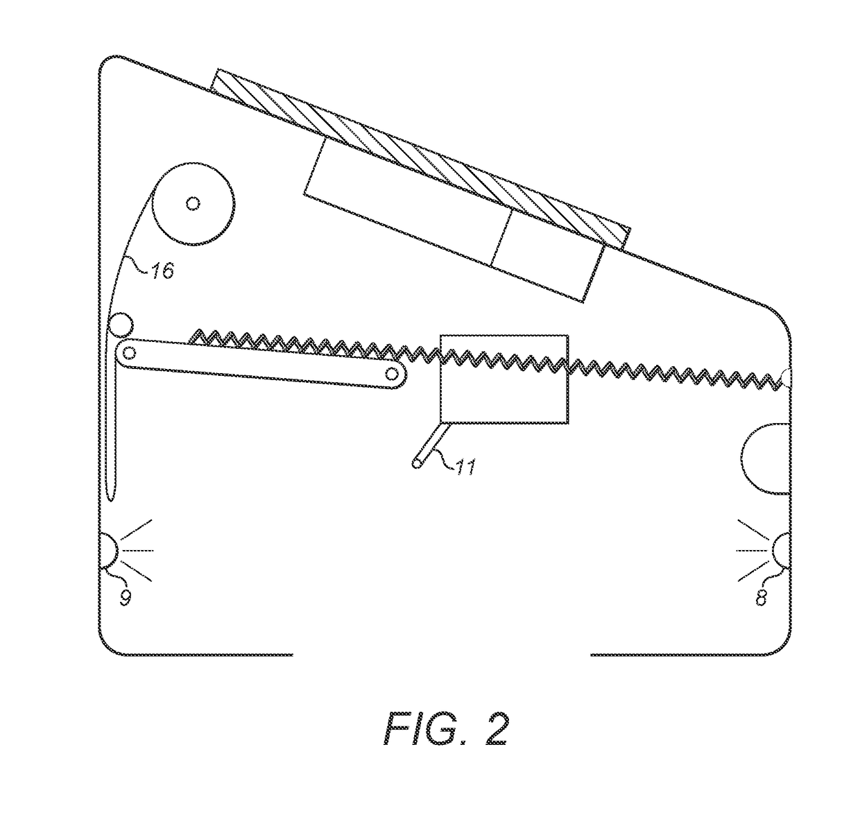
[0068]As shown in FIGS. 1 to 26, the present invention relates to a trap configured to kill a target creature, such as a mouse, rat, stoat, weasel, possum, rabbit, bird, toad, lizard, snake or other pest.

[0069]The trap 100 comprises a housing 1 that comprises at least one opening 10 for a target creature to at least partially enter the trap 100. The opening 10 may be provided at any suitable location on the trap 100 to allow a target creature to enter the trap through the opening 10. For example, the opening may be provided on an upper surface of the trap, a side surface, or a lower surface of the trap. In one form, the opening may span across more than one surface, such as when the opening is provided at a corner of the housing. In another form, the trap 100 may comprise multiple openings. In one form, as illustrated, the opening 10 is provided at the bottom of the trap 100, on a lower surface of the housing 1.

[0070]The housing 1 should be mounted in a suitable way to allow a targe...


PUM


Abstract

The invention relates to a trap, which may be a self-setting trap comprising a lockout system configured to prevent the actuation system of the trap from activating a strike member when an energy level of the power supply is below a predetermined threshold. In this way, the trap may be configured to kill an animal quickly, strongly and therefore as humanely as possible. In one embodiment, the trap may comprise a shock absorbing system to protect sensitive components of the trap when the strike member is activated.

Description

FIELD OF THE INVENTION[0001]The present invention relates to a trap for trapping target creatures.BACKGROUND TO THE INVENTION[0002]Management of ecosystems, farming systems, pest control and so forth can require a number of tasks to be performed to control target creatures, such as pests. These tasks may include traps to kill the target creatures.[0003]However, many traps typically require a regular program of maintenance by a worker. For example, in the case of a kill trap, the trap needs to be checked regularly to remove any dead creatures, to reset the trap and replace the lure.[0004]It is an object of the invention to provide a trap that goes at least some way towards overcoming the disadvantages of the prior art, or that at least provides the public with a useful alternative.SUMMARY OF THE INVENTION[0005]In one form, the invention comprises a trap comprising: at least one trigger; a strike member; a power supply; an actuating system connected to the strike member and configured...

Claims


Application Information

Patent Timeline
Patent Type & Authority Applications(United States)
IPC IPC(8): A01M23/24A01M31/00
CPCA01M23/24A01M31/002A01M31/008A01M27/00A01M23/245
Inventor REDMAYNE, JOHN MICHAEL
Owner REDMAYNE JOHN MICHAEL
Why Eureka
Try Eureka