Technique for collecting and measuring oil drained from a vehicle

a technology for collecting and measuring oil, which is applied in the direction of engine components, engine levels, mechanical equipment, etc., can solve the problems of vehicle being driven with an insufficient amount of oil, oil leakage from an engine, and most technicians do not even check the dipstick, etc., to facilitate oil consumption testing

Active Publication Date: 2018-11-22
SCHALLER ARTHUR D
View PDF14 Cites 3 Cited by
  • Summary
  • Abstract
  • Description
  • Claims
  • Application Information

AI Technical Summary

Benefits of technology

[0023]Advantages of the present invention may include one or more of the following:
[0024]The present invention allows the vehicle technician to be more proactive in visually spotting oil consumption problems in vehicles.
[0025]Moreover, the present invention may also be used to facilitate oil consumption testing, e.g., requested by a vehicle manufacturer in cases where a vehicle appears to be losing oil in a manner inconsistent with the vehicle's design specifications.

Problems solved by technology

Most technicians do not even check the dip stick to determine the amount of oil in the motor.
Moreover, oil may leak from an engine.
As vehicles get older, many times the motorist's vehicle can lose multiple quarts of oil between oil changes, which many times results in the vehicle being driven with an insufficient amount of oil, e.g., which is well below the recommended oil level specification for the vehicle.
By way of example, driving a vehicle with an insufficient amount of oil may cause damage to the vehicle when being operated, including damage to engine parts / components (e.g., rings) from the dirty oil concentrated in the smaller remaining quantity of oil, as well as damage from the vehicle running at much hotter temperatures than it otherwise should be running based upon recommended temperature operating specification for the vehicle.

Method used


Image

  • Technique for collecting and measuring oil drained from a vehicle
  • Technique for collecting and measuring oil drained from a vehicle
  • Technique for collecting and measuring oil drained from a vehicle

Examples


Embodiment Construction

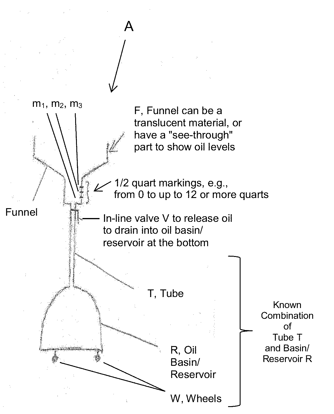
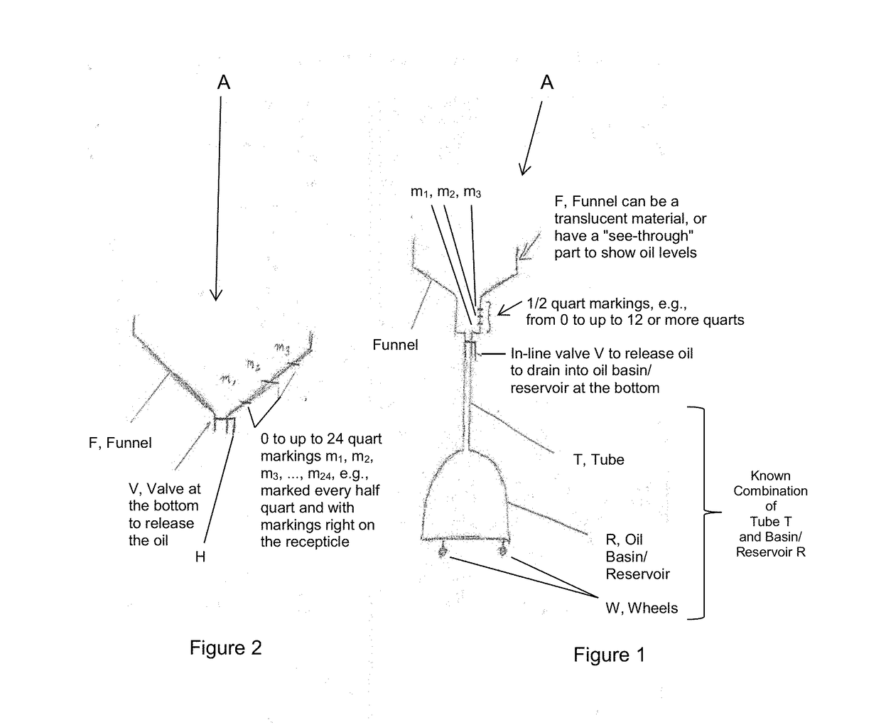
[0031]In summary, the apparatus / device disclosed herein is a new adaptation on a top portion (not shown) of an oil drain bucket that is currently known and used in the art, which includes the combination of an oil basin / reservoir and a tube as shown in FIG. 1, e.g., where the top portion (not shown) simply catches the oil and allows it to drain into the oil basin / reservoir below. This known combination is used in service stations that do oil changes throughout the United States and worldwide.

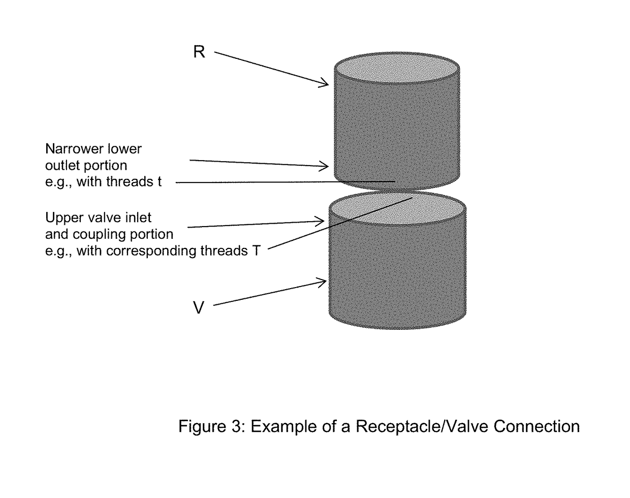
[0032]According to the present invention, a new and unique apparatus generally indicated as A has a new funnel or funnel section F that is created and configured at the top of the oil drain bucket, e.g., as shown in FIGS. 1 and 2. By way of example, this new and unique funnel section F may be made from a translucent or light colored plastic to allow the technician to see the amount of oil drained from the vehicle. This new and unique funnel section F has a valve V as shown configured at the bott...


PUM


Abstract

Apparatus for collecting and measuring oil drained from a vehicle includes a receptacle and a valve. The receptacle includes a wide upper oil collection portion with an upper receptacle wall configured to collect and contain oil drained from a vehicle, and includes a narrower lower outlet portion having a lower receptacle wall configured to allow the oil to drain from the receptacle via a gravity feed. The receptacle has markings arranged on at least one of the upper receptacle wall or the lower receptacle wall and configured to measure the oil drained and collected from the vehicle. The valve includes an upper valve inlet and coupling portion configured to connect to the narrower lower outlet portion of the receptacle and allow the oil to drain into the valve, includes a valve opening/closing portion configured either to open and allow the oil to drain through the valve or to close and allow oil to collect in the receptacle, and includes a lower valve outlet and coupling portion configured to connect to a tube or oil basin/reservoir to allow the oil to drain from the valve into the tube or oil basin/reservoir.

Description

CROSS-REFERENCE TO RELATED APPLICATIONS[0001]This application claims benefit to provisional patent application Ser. No. 62 / 509,504, filed 22 May 2017, as well as provisional patent application Ser. No. 62 / 674,721, filed 22 May 2018, which are both hereby incorporated by reference.BACKGROUND OF THE INVENTION1. Field of the Invention[0002]This application relates to a technique for collecting and measuring oil drained from a vehicle.2. Description of Related Art[0003]In the prior art, when a motorist has their oil changed, a technician typically drains the oil from the motorist's vehicle into an oil basin, e.g., without having any idea how much oil was drained from the consumer's vehicle. Most technicians do not even check the dip stick to determine the amount of oil in the motor.[0004]As one skilled in the art would appreciate, when vehicles are operated during normal use, engines burn or consume oil. Moreover, oil may leak from an engine. As vehicles get older, many times the motori...

Claims


Application Information

Patent Timeline
Patent Type & Authority Applications(United States)
IPC IPC(8): F01M11/04F01M11/12F16N31/02
CPCF01M11/04F01M11/12F16N31/02F16N2250/18F16N2230/18F16N2280/00
Inventor SCHALLER, ARTHUR D.
Owner SCHALLER ARTHUR D
Why Eureka
Try Eureka