
System and method for operating a packaged terminal air conditioner unit

a terminal and packaged technology, applied in ventilation systems, lighting and heating apparatus, heating types, etc., can solve the problems of auxiliary fans that may not be able to provide a sufficient flow rate of make-up air, auxiliary fans may generate too much noise, and consume too much energy

Active Publication Date: 2018-12-06
HAIER US APPLIANCE SOLUTIONS INC
View PDF11 Cites 3 Cited by
  • Summary
  • Abstract
  • Description
  • Claims
  • Application Information

AI Technical Summary

Benefits of technology

The present invention relates to a packaged terminal air conditioner unit (PTAC) and a method for operating it. The PTAC includes a vent aperture and an auxiliary fan for urging a flow of make-up air through the vent aperture. The controller is designed to obtain a room occupancy status and determine a target make-up air flow rate based on the status. The controller operates an exhaust fan to urge a flow of exhaust air through an exhaust duct at an exhaust flow rate and the auxiliary fan to urge the flow of auxiliary air at an auxiliary flow rate. The target make-up air flow rate is the difference between the exhaust flow rate and the auxiliary flow rate. The invention provides a more efficient and effective air conditioning system for room that can adjust the make-up air flow rate based on the occupancy status and ensure a comfortable and healthy air condition.

Problems solved by technology

In certain situations, the auxiliary fan may not be capable of providing a sufficient flow rate of make-up air to meet the room requirements.
Alternatively, the auxiliary fan may generate too much noise or consume too much energy when trying to supply higher flow rates of make-up air.

Method used


Image

  • System and method for operating a packaged terminal air conditioner unit
  • System and method for operating a packaged terminal air conditioner unit
  • System and method for operating a packaged terminal air conditioner unit

Examples


Embodiment Construction

[0021]Reference now will be made in detail to embodiments of the invention, one or more examples of which are illustrated in the drawings. Each example is provided by way of explanation of the invention, not limitation of the invention. In fact, it will be apparent to those skilled in the art that various modifications and variations can be made in the present invention without departing from the scope or spirit of the invention. For instance, features illustrated or described as part of one embodiment can be used with another embodiment to yield a still further embodiment. Thus, it is intended that the present invention covers such modifications and variations as come within the scope of the appended claims and their equivalents.

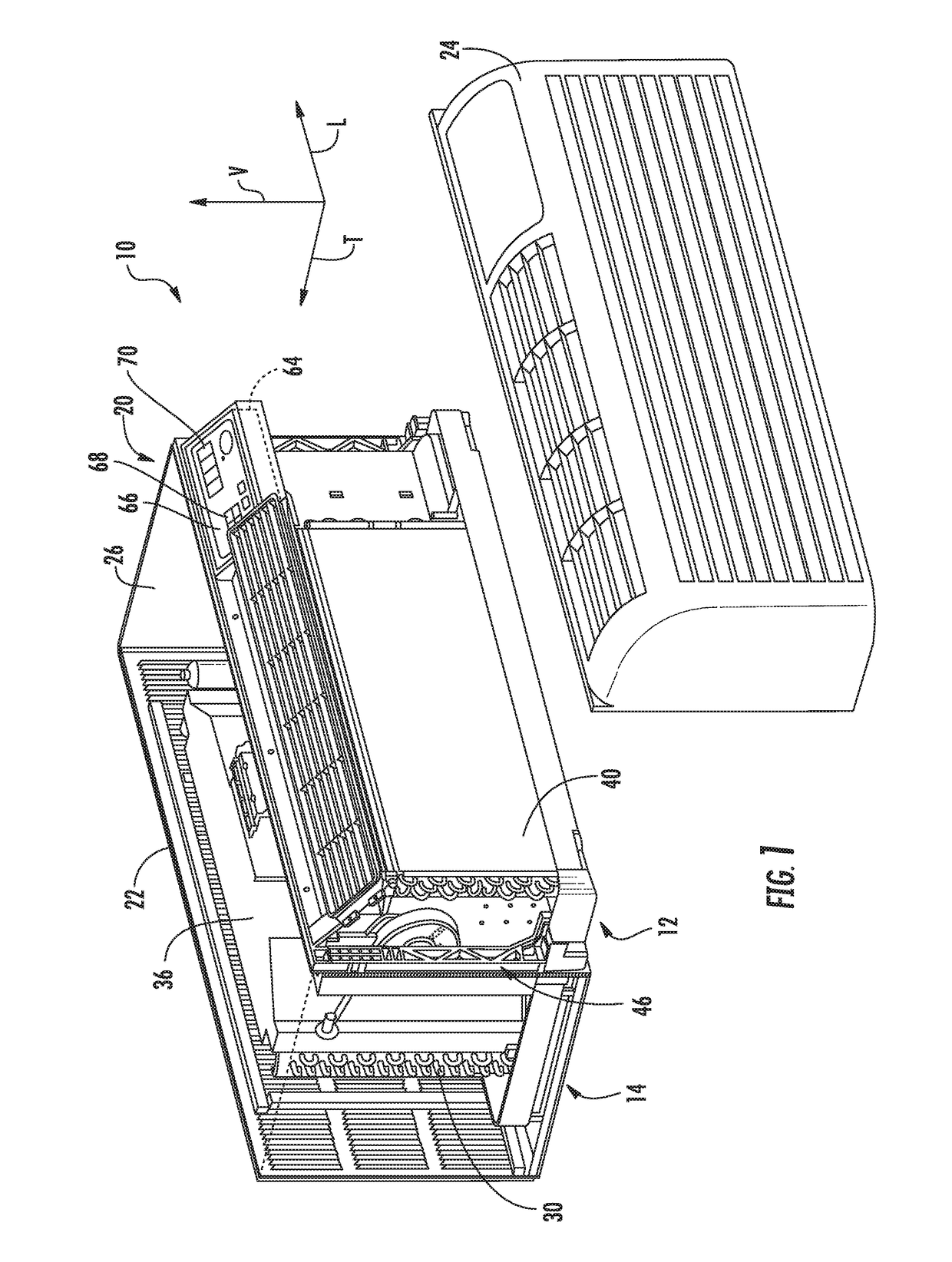
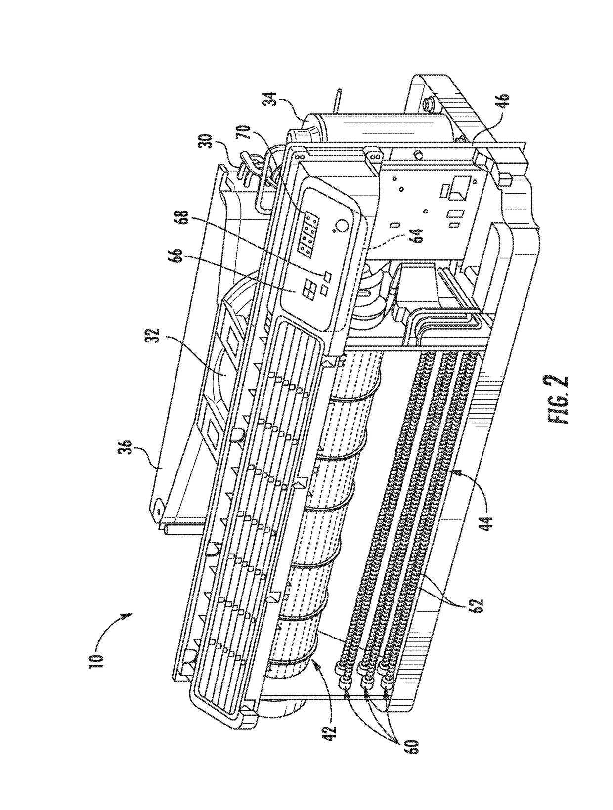
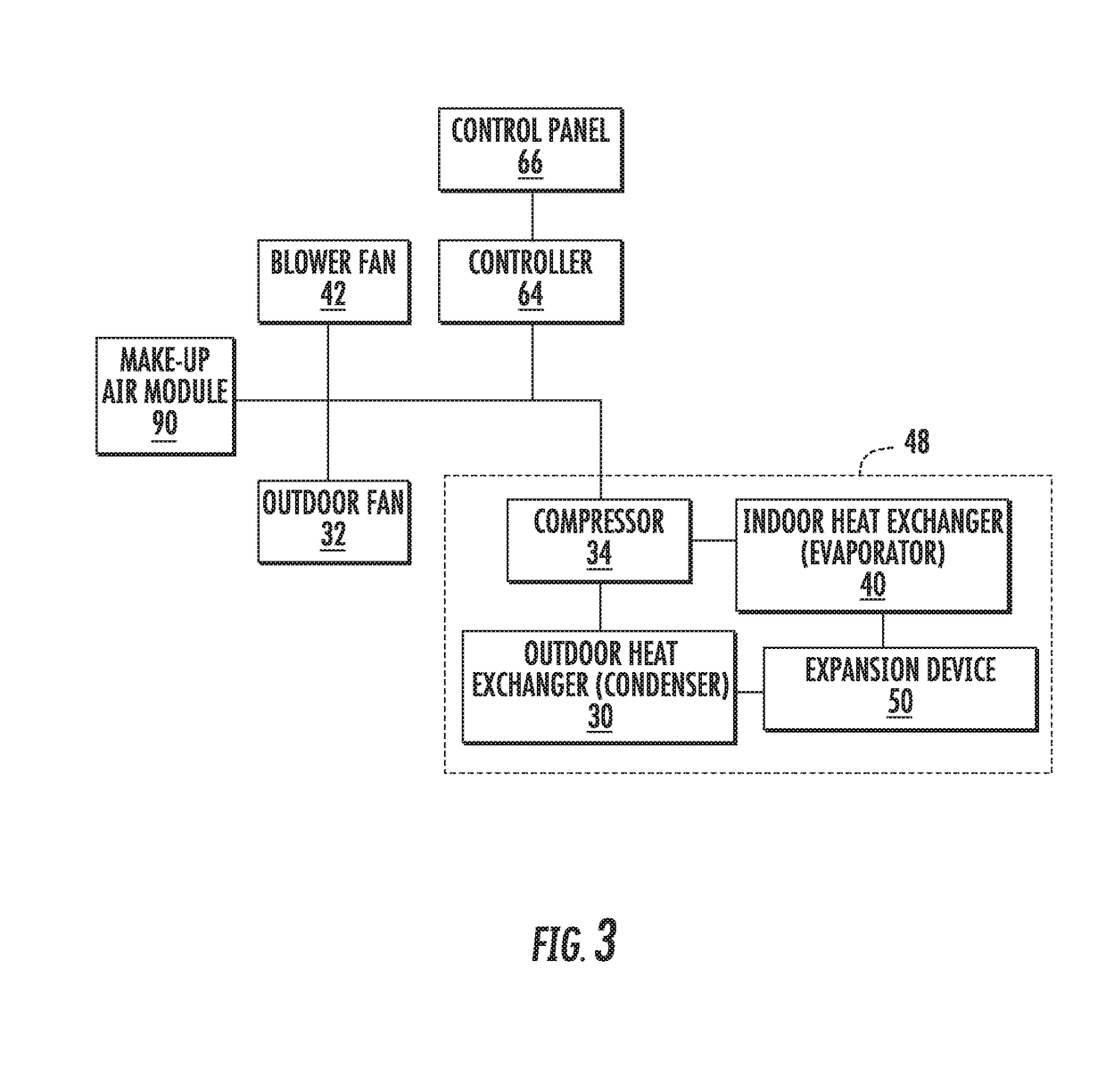
[0022]Referring now to FIG. 1, an air conditioner unit 10 is provided. The air conditioner unit 10 is a one-unit type air conditioner, also conventionally referred to as a room air conditioner or a packaged terminal air conditioner (PTAC). The unit 10 inclu...


PUM


Abstract

A packaged terminal air conditioner unit (PTAC) and methods for operating the same are provided. The PTAC includes a vent aperture defined in a bulkhead of the PTAC and an auxiliary fan for urging a flow of make-up air through the vent aperture. A controller is configured for obtaining a room occupancy status from an occupancy system and determining a target make-up air flow rate based on the room occupancy status. The controller operates an exhaust fan, such as a bathroom fan, to urge a flow of exhaust air through an exhaust duct at an exhaust flow rate and operates the auxiliary fan to urge the flow of auxiliary air at an auxiliary flow rate, the auxiliary flow rate being substantially equivalent to the target make-up air flow rate minus the exhaust flow rate.

Description

FIELD OF THE INVENTION[0001]The present disclosure relates generally to air conditioner units, and more particularly to packaged terminal air conditioner units and related methods of operation.BACKGROUND OF THE INVENTION[0002]Air conditioner or conditioning units are conventionally utilized to adjust the temperature indoors—i.e. within structures such as dwellings and office buildings. Such units commonly include a closed refrigeration loop to heat or cool the indoor air. Typically, the indoor air is recirculated while being heated or cooled. A variety of sizes and configurations are available for such air conditioner units. For example, some units may have one portion installed within the indoors that is connected, by e.g., tubing carrying the refrigerant, to another portion located outdoors. These types of units are typically used for conditioning the air in larger spaces.[0003]Another type of unit, sometimes referred to as a packaged terminal air conditioner unit (PTAC), may be u...

Claims


Application Information

Patent Timeline
IPC IPC(8): F24F11/00F24F1/02F24F7/013
CPCF24F11/0001F24F2011/0002F24F7/013F24F1/027F24F11/56F24F11/72F24F2120/10
Inventor FRADKIN, MIKE
Owner HAIER US APPLIANCE SOLUTIONS INC
Learn More