Additive manufacturing apparatus

Active Publication Date: 2019-04-25
GENERAL ELECTRIC CO
View PDF0 Cites 12 Cited by
  • Summary
  • Abstract
  • Description
  • Claims
  • Application Information

AI Technical Summary

Problems solved by technology

However, there are challenges associated with unloading the newly formed components, which must occur prior to forming the next batch of components.
Conventional additive manufacturing apparatus typically require operators to open the apparatus to manually remove the loose powder material, which is time-consuming.
More

Method used


Image

  • Additive manufacturing apparatus
  • Additive manufacturing apparatus
  • Additive manufacturing apparatus

Examples


Embodiment Construction

[0026]Provided are exemplary additive manufacturing apparatus. Embodiments of the present disclosure, in comparison to additive manufacturing apparatus not utilizing one or more features disclosed herein, decrease component cycle time, decrease operating costs, improve operator working conditions, decrease risk of powder material contamination, or combinations thereof.

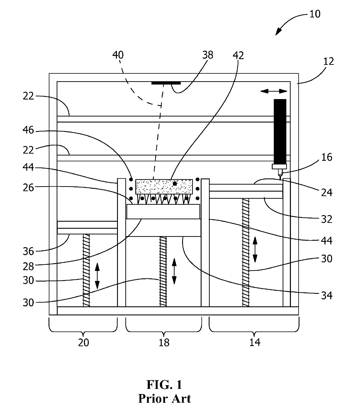
[0027]Referring to FIG. 1, a prior art additive manufacturing apparatus 10 includes an enclosure or operating envelope 12 containing a powder dispenser area or powder dispenser container / volume 14, a component building area 18, and a powder recovery arrangement 20. A typical manufacturing apparatus layout / architecture for medium size DMLM machines like Model 290 manufactured by Electro Optical Systems (EOS) or M2, M1 models manufactured by Concept Laser. Component building area 18 includes opposed walls 44 Operating envelope 12 includes guides 22 for carrying a powder recoater 16 between powder dispenser container / volu...


PUM

PropertyMeasurementUnit
Flexibilityaaaaaaaaaa
Areaaaaaaaaaaa
Heightaaaaaaaaaa

Abstract

An additive manufacturing apparatus includes an energy beam source adapted to emit an energy beam, and a component building area including a base extendable between and vertically movable relative to opposed walls. The component building area includes a platform supported by the base and extendable between the walls, the platform having a layer onto which powdered material is applied, the powdered material being melted or sintered by the energy beam to form a component. The component building area includes an articulation device for rotating the platform about a horizontal axis, and a powder recovery arrangement. The apparatus includes subsequent to formation of the component, the articulation device rotating the platform about the horizontal axis for collecting loose powder by the powder recovery arrangement by virtue of gravity.

Description

FIELD OF THE INVENTION[0001]The present invention is directed to additive manufacturing apparatus. More particularly, the present invention is directed to additive manufacturing apparatus and method for operating manufacturing apparatus forming components from powder material.BACKGROUND OF THE INVENTION[0002]Additive manufacturing apparatus, such as direct metal laser melting (DMLM) are utilized to form components for use in many applications. Many additive manufacturing apparatus utilize a laser beam to melt or sinter sequentially arranged layers of the powder material to form such components. However, there are challenges associated with unloading the newly formed components, which must occur prior to forming the next batch of components.[0003]For example, loose powder material must be collected from the component building area of the apparatus. Conventional additive manufacturing apparatus typically require operators to open the apparatus to manually remove the loose powder mater...

Claims


Application Information

Patent Timeline
IPC IPC(8): B29C64/245B29C64/153B29C64/268B29C64/241
CPCB29C64/245B29C64/153B29C64/268B29C64/241B22F3/10B29C64/35B29C64/25B33Y10/00B33Y30/00B33Y40/00B29C64/357B22F3/24B22F2003/247Y02P10/25B22F10/28B22F12/37B22F10/73B33Y40/20
Inventor BOBAR, ADNANSCHWERDTFEGER, JANHARO, JUAN VICENTESWANNER, JR., ARCHIE
Owner GENERAL ELECTRIC CO
Why Eureka
Try Eureka