Frame structure, fan and motor

a frame structure and fan technology, applied in the direction of machines/engines, liquid fuel engines, instruments, etc., can solve the problems of affecting the lifetime of the fan body, affecting the increasing the weight of the frame structure, so as to improve the motion stability of the cantilever, and reduce the vibration of a certain bandwidth

Active Publication Date: 2019-05-02
DELTA ELECTRONICS INC
View PDF1 Cites 0 Cited by
  • Summary
  • Abstract
  • Description
  • Claims
  • Application Information

AI Technical Summary

Benefits of technology

[0030]In addition, the configuration of the vibration structure can eliminate the vibration of a certain bandwidth. The shape and amount of the cantilevers can increase the absorbed vibration bandwidth. The configuration of the support column can improve the motion stability of the cantilevers. These configurations can achieve an effective damping effect, increase the lifetime of the fan and motor, and enhance the performance of the entire system.

Problems solved by technology

However, the generated vibration during the high-speed rotation of the fan can be delivered to the peripheral devices of the fan, which can influence the performance of the fan assembly system.
In particularly, when the vibration frequency is approaching to the natural frequency of the frame structure, the fan will generate a serious resonance, which can affect the lifetime of the fan body and damage the peripheral devices.
However, the above-mentioned methods for providing the damping function will increase the weight of the frame structure.
However, the buffering material will become aged and deterioration after a certain of time, and it will have a greater deformation under the environment of high temperature and heavy loading, which may affect the reliability of the high-speed rotation fan.

Method used


Image

  • Frame structure, fan and motor
  • Frame structure, fan and motor
  • Frame structure, fan and motor

Examples


Embodiment Construction

[0041]The present invention will be apparent from the following detailed description, which proceeds with reference to the accompanying drawings, wherein the same references relate to the same elements.

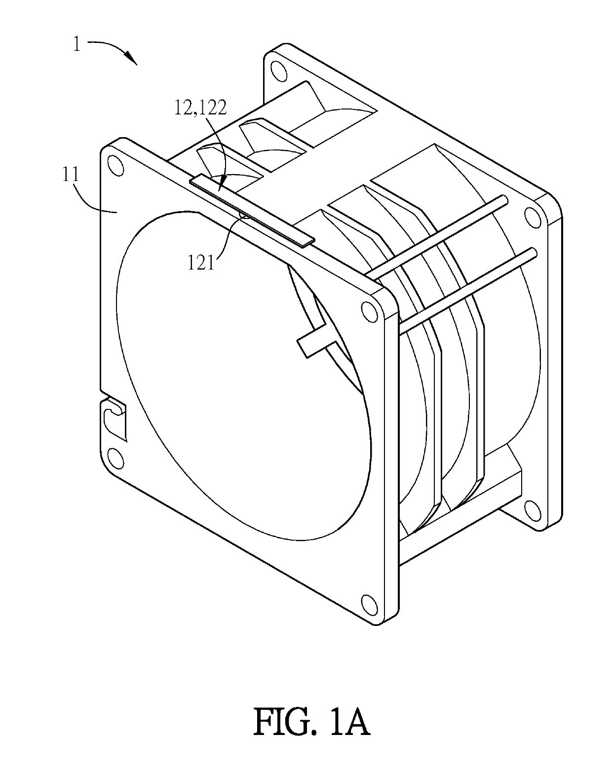
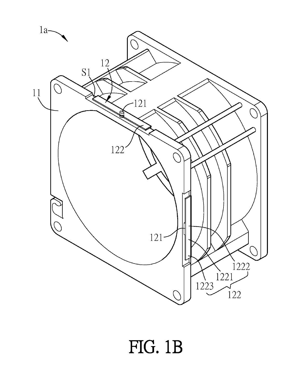
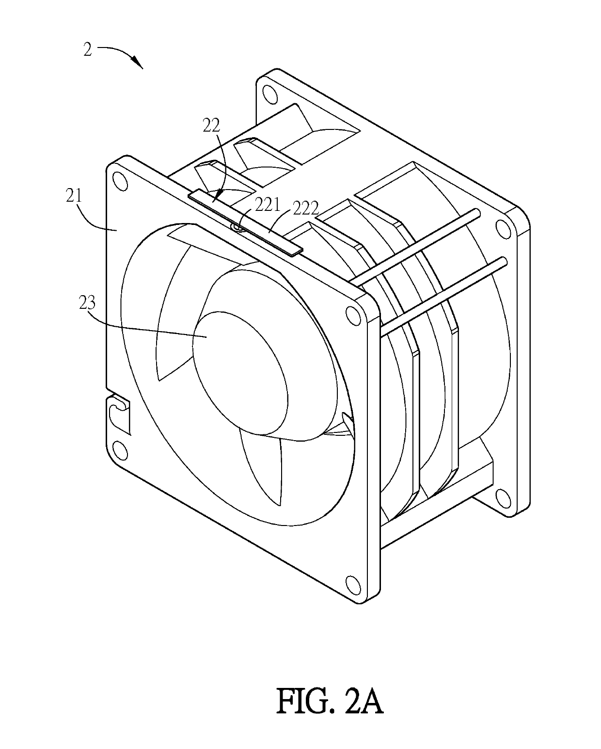
[0042]The following embodiments will be described with reference to FIGS. 1A, 1B, 2A, 2B and 2C. FIG. 1A is a schematic diagram showing a frame structure according to an embodiment of the disclosure. FIG. 1B is a schematic diagram showing a frame structure according to another embodiment of the disclosure. FIG. 2A is a schematic diagram showing a fan according to an embodiment of the disclosure. FIG. 2B is a schematic diagram showing a fan according to another embodiment of the disclosure. FIG. 2C is a schematic diagram showing a fan according to another embodiment of the disclosure, wherein the vibration absorbing structure of the frame structure is different from that shown in FIG. 2A. In order to make the drawings more clear, the driving devices of the fans 2, 2a and 2b are not sho...


PUM


Abstract

A frame structure includes a frame body and at least one vibration absorbing structure. The vibration absorbing structure has a support column and at least one cantilever. The cantilever has a cantilever body, a first end portion and a second end portion. One end of the support column is connected to a wall surface of the frame body. The first end portion of the cantilever is connected to the support column. The cantilever body and the second end portion extend outwardly and swing freely on the wall surface of the frame body. When the cantilever body and the second end portion are swinging, they are not in contact with any peripheral member and the frame structure.

Description

CROSS REFERENCE TO RELATED APPLICATIONS[0001]This Non-provisional application claims priority under 35 U.S.C. § 119(a) on Patent Application No(s). 201711027644.X filed in People's Republic of China on Oct. 27, 2017, the entire contents of which are hereby incorporated by reference.BACKGROUND OF THE INVENTIONField of Invention[0002]The disclosure relates to a frame structure, a fan and a motor, which includes a vibration absorbing structure.Related Art[0003]The fan is usually configured in an electric device for speeding the heat dissipation and achieving a higher heat dissipation efficiency. In general, the faster the rotation speed of the fan is, the higher the vibration frequency is induced. However, the generated vibration during the high-speed rotation of the fan can be delivered to the peripheral devices of the fan, which can influence the performance of the fan assembly system. In particularly, when the vibration frequency is approaching to the natural frequency of the frame ...

Claims


Application Information

Patent Timeline
Patent Type & Authority Applications(United States)
IPC IPC(8): F04D29/66G06F1/20
CPCF04D29/668G06F1/20F04D29/601H05K7/20172F04D25/0613F04D29/661
Inventor CHEN, KUN-HUNGTUNG, PAO-HUNGLEI, TSUNG-YU
Owner DELTA ELECTRONICS INC
Why Eureka
Try Eureka