Suction device for a wastewater tank

Active Publication Date: 2019-05-16
HUGO VOGELSANG MASCHINENBAU GMBH
View PDF5 Cites 0 Cited by
  • Summary
  • Abstract
  • Description
  • Claims
  • Application Information

AI Technical Summary

Benefits of technology

[0043]Finally, it is further preferred if the suction-extraction operation is reversed when a blockage occurs or at regular intervals, and in the process liquid, in particular, wastewater, is introduced into the was

Problems solved by technology

The disadvantage with this procedure is that the coach is sometimes not placed precisely in position, as a result of which the discharge opening does not end up located precisely above the opening in the ground and therefore the region around the opening in the ground is contaminated.
Although, as a result, the positioning accuracy is improved, it is nevertheless the case that the poor visibility can result in incorrect operation, which leads to contamination.
In addition, the device already known from DE 20 2015 103 442 U1 requires a catching hopper, which is contaminated by the wastewater being discharged and, therefore, renders subsequent cleaning necessary.
Nevertheless, it is also occasionally the case that contamination and odor-related problems occur with this method of emptying the wastewater-collection tank.
The disadvantage with this configuration is that the feed of the wastewater from the wastewater-collection tank into the suction-extraction arrangement has to be arranged at a considerable height in r

Method used


Image

  • Suction device for a wastewater tank
  • Suction device for a wastewater tank
  • Suction device for a wastewater tank

Examples


second embodiment

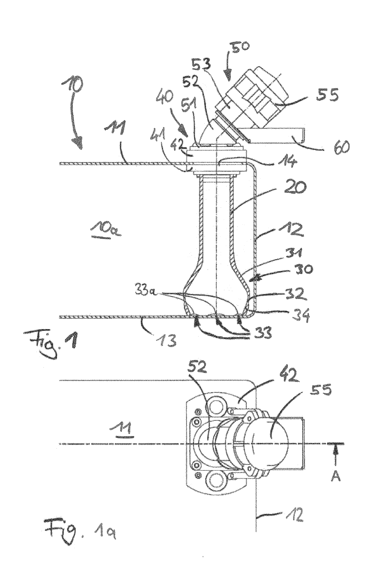
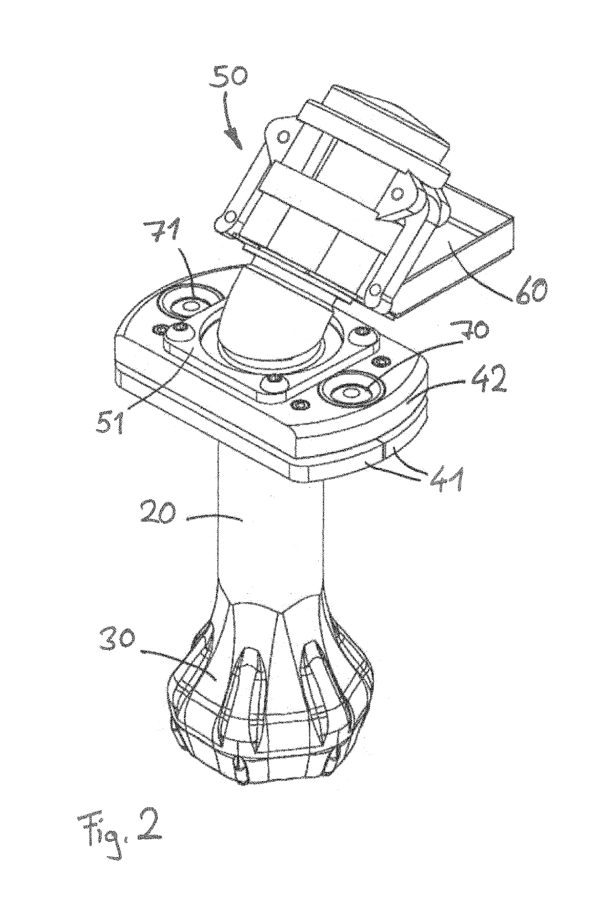
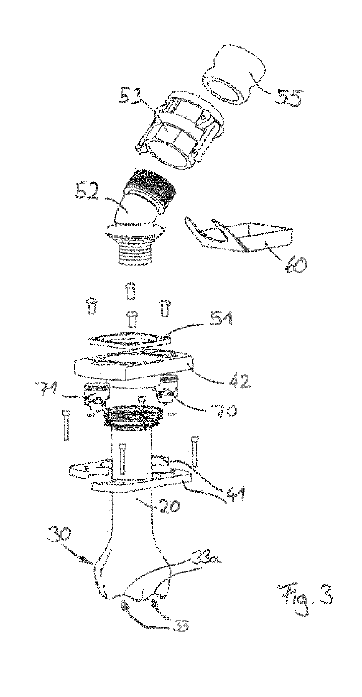
[0070]It is also the case with the second embodiment that a suction tube 120 extends downward within the wastewater-collection tank 10, starting from a lower flange-connection plate 141, and is formed in one piece with a suction bell 130.

first embodiment

[0071]It is likewise the case that the suction bell 130 is seated on the floor, but in contrast to the suction bell 30 of the first embodiment, which is designed concentrically and in a rotationally symmetrical manner in relation to the suction tube 20, suction bell 130 is designed eccentrically and in a rotationally non-symmetrical manner. Instead, the suction bell 130 terminates flush with a sidewall portion of the suction tube 120 and extends horizontally only over approximately 270°, in such a manner that its cross section exceeds the cross section of the suction tube. The suction bell 130 may be of semicircular or circular cross section, although other geometries, including mixtures of these or polygonal configurations, are also possible.

[0072]It is likewise the case that the suction bell 130 rests on the floor wall 113, and, in this case, is retained in a propped-up state by a plurality of feet 135. The feet 135 delimit suction-extraction openings 133, which are each formed be...

third embodiment

[0073]FIGS. 6 and 6a show the invention, which, as far as the connection coupling 250 and fastening flange 240 are concerned, is, once again, structurally identical to the connection coupling 50 and fastening flange 40 explained above. Like the embodiment according to FIGS. 5 and 5a, the embodiment according to FIGS. 6 and 6a is equipped with an eccentric suction bell 230, which once again is formed in one piece on a suction tube 220. The suction bell 230 has a geometry that is different to that of the suction bell 130 shown in FIGS. 5 and 5a, but, like the suction bell according to FIGS. 5 and 5a, it is provided along its lower edge with a plurality of apertures 233, which are arranged between respective feet 235. These feet 235 are elastically deformable and, when there is an increase in negative suction pressure in the interior of the suction bell, can swing in in the inward direction in order to provide an increased through-passage cross section through the apertures 233.

[0074]F...


PUM

PropertyMeasurementUnit
Fractionaaaaaaaaaa
Angleaaaaaaaaaa
Angleaaaaaaaaaa

Abstract

The invention relates to a sanitary arrangement, in particular, a mobile sanitary arrangement in a motor vehicle such as a coach, having a wastewater-collection tank which has a floor and a sidewall that enclose a tank interior, and an inlet connection and an outlet device. The outlet device has an outlet opening with a connection coupling for the connection of a suction-extraction arrangement and a suction-extraction channel, which, starting from the outlet opening, extends downward in the direction of gravitational force to an intake opening within the wastewater-collection tank.

Description

CROSS REFERENCE TO FOREIGN PRIORITY DOCUMENT[0001]The present application claims the benefit under 35 U.S.C. §§ 119(b), 119(e), 120, 121, 365(c), and / or 386(c) of PCT / EP2017 / 06081 filed Apr. 27, 2017, which claims priority to German Application DE 202016102246.0 filed Apr. 27, 2016.FIELD OF THE INVENTION[0002]The present disclosure relates to a sanitary arrangement, in particular a mobile sanitary arrangement in a motor vehicle such as a coach, having a wastewater-collection tank, which has a floor and a side wall, which enclose a tank interior, and also an inlet connection and an outlet device. A further aspect of the present disclosure is a wastewater-collection tank for such a sanitary arrangement and also a retrofittable suction-extraction arrangement for a wastewater-collection tank in such a sanitary arrangement.BACKGROUND OF THE INVENTION[0003]Wastewater-collection tanks of sanitary arrangements are used for stationary units, for example, water closet (“WC”) arrangements for ...

Claims


Application Information

Patent Timeline
IPC IPC(8): E03F1/00B60R15/04
CPCE03F1/008B60R15/04B61D35/007B01D29/055B01D35/147B01D35/1475B65D83/32B67D1/0802Y10T137/8085Y10T137/86348Y10T137/86372
Inventor ZEIN, BILALHEINRICHS, MARTIN
Owner HUGO VOGELSANG MASCHINENBAU GMBH
Why Eureka
Try Eureka