Suction device for a wastewater tank
a technology for suction devices and wastewater tanks, applied in the field of sanitary arrangement, can solve problems such as contamination of the region around the opening in the ground, incorrect operation, contamination and odor-related problems, and achieve the effect of reducing the cross-section of the through-passage intake openings
- Summary
- Abstract
- Description
- Claims
- Application Information
AI Technical Summary
Benefits of technology
Problems solved by technology
Method used
Image
Examples
second embodiment
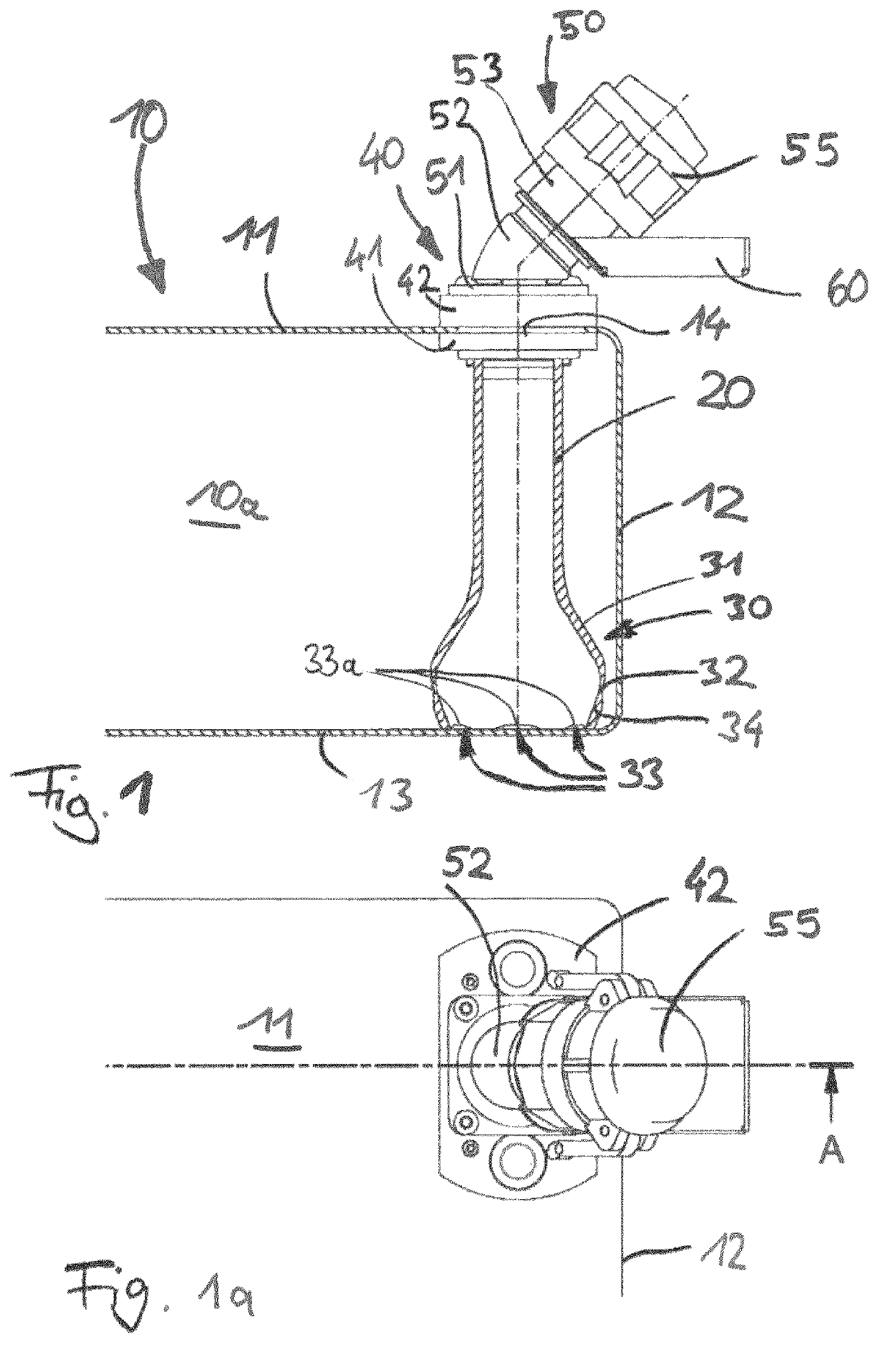
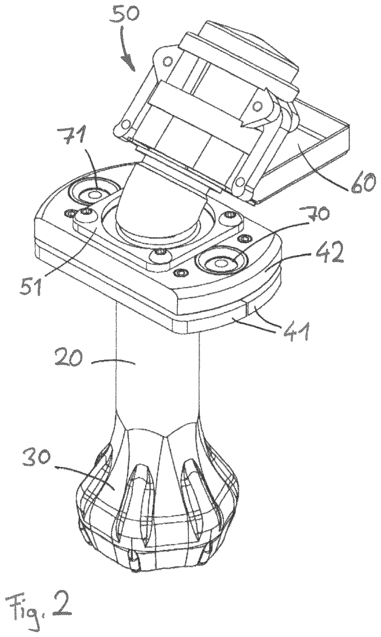
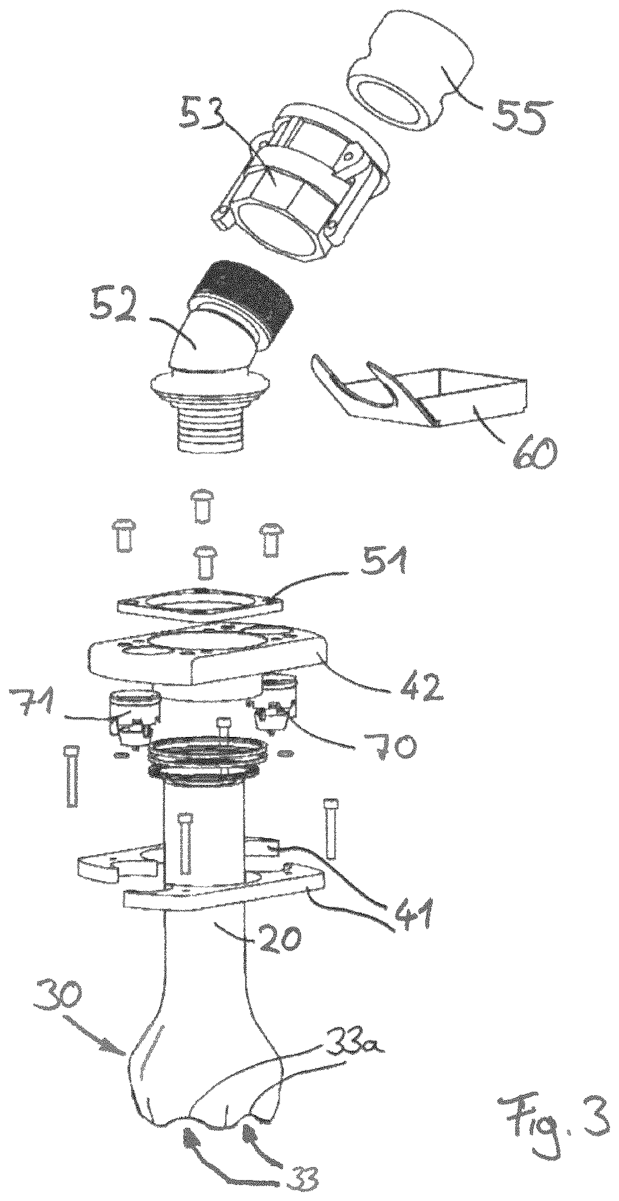
[0070]It is also the case with the second embodiment that a suction tube 120 extends downward within the wastewater-collection tank 10, starting from a lower flange-connection plate 141, and is formed in one piece with a suction bell 130.
first embodiment
[0071]It is likewise the case that the suction bell 130 is seated on the floor, but in contrast to the suction bell 30 of the first embodiment, which is designed concentrically and in a rotationally symmetrical manner in relation to the suction tube 20, suction bell 130 is designed eccentrically and in a rotationally non-symmetrical manner. Instead, the suction bell 130 terminates flush with a sidewall portion of the suction tube 120 and extends horizontally only over approximately 270°, in such a manner that its cross section exceeds the cross section of the suction tube. The suction bell 130 may be of semicircular or circular cross section, although other geometries, including mixtures of these or polygonal configurations, are also possible.
[0072]It is likewise the case that the suction bell 130 rests on the floor wall 113, and, in this case, is retained in a propped-up state by a plurality of feet 135. The feet 135 delimit suction-extraction openings 133, which are each formed be...
third embodiment
[0073]FIGS. 6 and 6a show the invention, which, as far as the connection coupling 250 and fastening flange 240 are concerned, is, once again, structurally identical to the connection coupling 50 and fastening flange 40 explained above. Like the embodiment according to FIGS. 5 and 5a, the embodiment according to FIGS. 6 and 6a is equipped with an eccentric suction bell 230, which once again is formed in one piece on a suction tube 220. The suction bell 230 has a geometry that is different to that of the suction bell 130 shown in FIGS. 5 and 5a, but, like the suction bell according to FIGS. 5 and 5a, it is provided along its lower edge with a plurality of apertures 233, which are arranged between respective feet 235. These feet 235 are elastically deformable and, when there is an increase in negative suction pressure in the interior of the suction bell, can swing in in the inward direction in order to provide an increased through-passage cross section through the apertures 233.
[0074]F...
PUM
| Property | Measurement | Unit |
|---|---|---|
| distance | aaaaa | aaaaa |
| distance | aaaaa | aaaaa |
| distance | aaaaa | aaaaa |
Abstract
Description
Claims
Application Information
 - R&D
- Intellectual Property
- Life Sciences
- Materials
- Tech Scout
- Unparalleled Data Quality
- Higher Quality Content
- 60% Fewer Hallucinations
Browse by: Latest US Patents, China's latest patents, Technical Efficacy Thesaurus, Application Domain, Technology Topic, Popular Technical Reports.
© 2025 PatSnap. All rights reserved.Legal|Privacy policy|Modern Slavery Act Transparency Statement|Sitemap|About US| Contact US: help@patsnap.com


