Screening arrangement with improved mounting bracket and end piece, window with such a mounting bracket and method of installing and uninstalling a screening arrangement in the window

a technology of mounting bracket and mounting end, which is applied in the direction of door/window protective devices, building components, constructions, etc., can solve the problems of making the mounting and dismounting of the mounting and end piece in turn even more difficult, and achieve the effect of facilitating the installation and dismounting conditions and retaining the stable engagemen

Active Publication Date: 2019-05-16
VKR HLDG AS
View PDF0 Cites 6 Cited by
  • Summary
  • Abstract
  • Description
  • Claims
  • Application Information

AI Technical Summary

Benefits of technology

[0008]It is therefore the object of the invention to provide facilitated installation and dismounting conditions while at the same time retaining the stable engagement in the position of use of the screening arrangement.
[0010]In this way, the screening device is safely retained on the mounting brackets during normal use, thus preventing unintentional release of the locking means. The resilient tab acts to keep the tab in the notch, either by the interaction between the end piece and the mounting bracket, or by pushing against an external surface such as a part of the frame and sash in which the screening arrangement is mounted. In this way, the cooperation between the tab and notch on one hand and the resilient tab on the other acts to provide a snap lock which is engaged in the mounted condition. In case the screening arrangement is to be dismounted, either to replace the screening device, or to remove the screening arrangement entirely, the user simply grabs the top element of the screening device, moves it in the height direction, against the bias of the resilient tab, such that the tab is withdrawn from the notch and pulls the screening device towards himself or herself, thus overcoming the locking function of the engagement between the tab and the notch. In other words, the snap lock is thus engaged until the user actively pulls the screening device, typically in the direction substantially perpendicularly away from the pane of the frame to be screened. This prevents any unintentional or untimely release of the screening device from the mounting brackets. During this procedure, there is no need for separate tools or to manipulate the locking means by hand.
[0011]In a presently preferred embodiment, the tab faces the resilient tab in the mounted condition and the resilient tab defines a height level in its relaxed condition, and the tab has a guiding surface located at a distance from the resilient tab in its relaxed condition and an abutment surface to interact with the notch of the mounting bracket, and wherein the mounting bracket includes a first ledge section protruding from the plane body portion and located at a first distance from an edge of the mounting bracket, said first distance being slightly smaller than the distance between the guiding surface of the tab and the resilient tab of the end piece in its relaxed condition, such that the set of locking means is able to be engaged in the mounted condition and be disengaged when the end piece is positioned in the removal position.
[0012]By incorporating a set of cooperating guides on the end pieces and the mounting brackets, respectively, the mounting and dismounting of the screening device from the mounting brackets and hence from the window is facilitated even further. The screening device with its end pieces is safely guided in the mounting direction until a distinct locking position occurs when the tab of the end pieces snaps into the notch of the respective mounting bracket by the action of the resilient tab. Conversely, when dismounting the screening arrangement, the user is able to withdraw the tab from the notch by moving the screening device in the height direction, against the bias of the resilient tab, due to the difference in distances, before pulling the screening device top element in the dismounting direction. Finally, the screening arrangement in this embodiment is independent of its position relative to the window in which it is mounted, and hence, slight deviations in the shape and size due to unavoidable tolerances of the window do not affect the functioning of the screening arrangement during mounting and dismounting.

Problems solved by technology

This is growing even more important as window tend to have larger dimensions, and the unavoidable production tolerances are thus increasing as well, rendering in turn the mounting and dismounting even more difficult.

Method used


Image

  • Screening arrangement with improved mounting bracket and end piece, window with such a mounting bracket and method of installing and uninstalling a screening arrangement in the window
  • Screening arrangement with improved mounting bracket and end piece, window with such a mounting bracket and method of installing and uninstalling a screening arrangement in the window
  • Screening arrangement with improved mounting bracket and end piece, window with such a mounting bracket and method of installing and uninstalling a screening arrangement in the window

Examples


Embodiment Construction

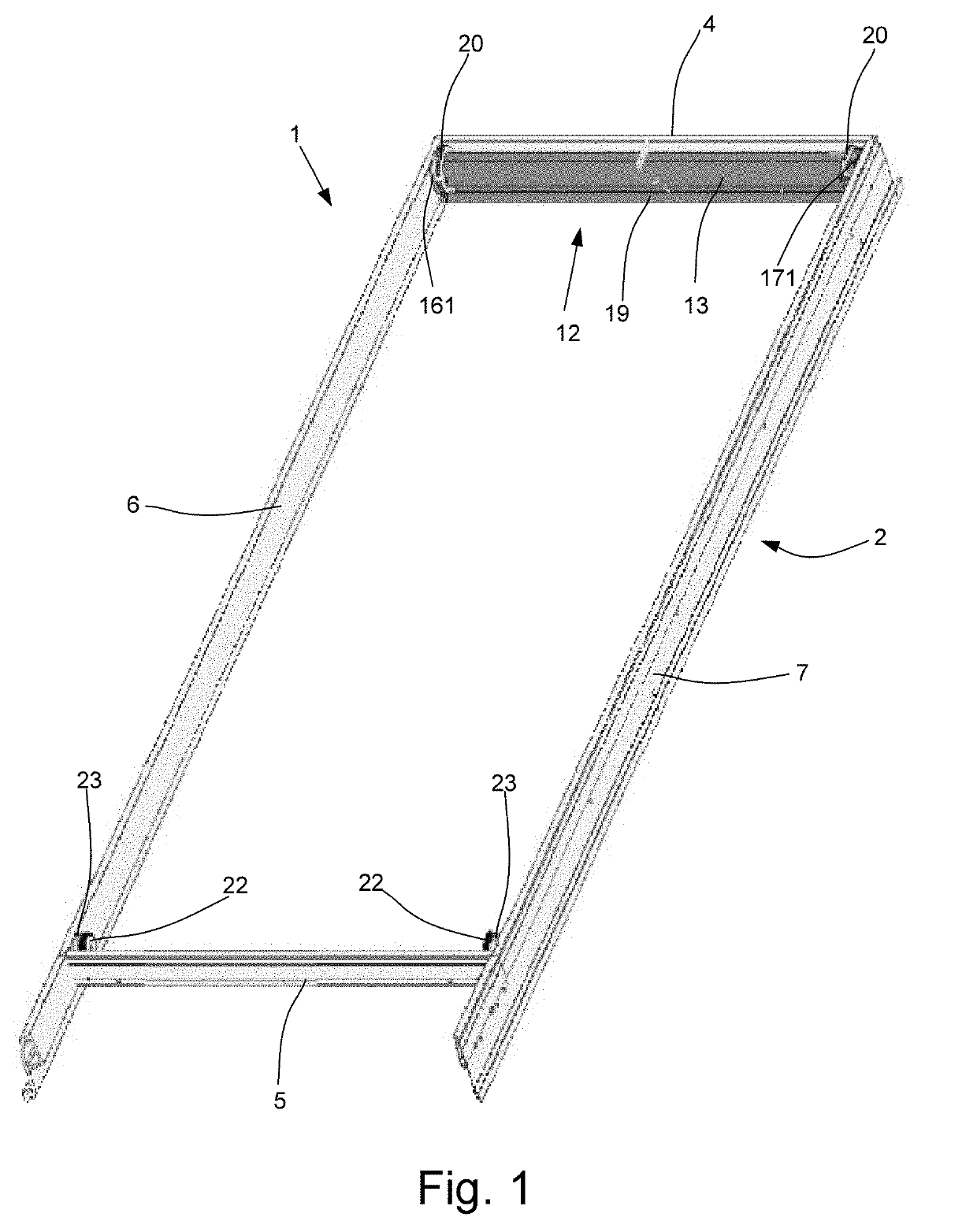
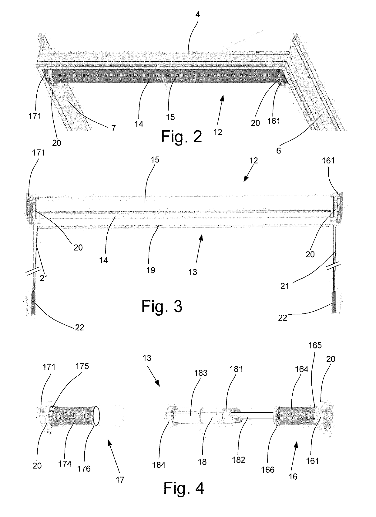
[0030]Referring initially to FIGS. 1 and 2, a first embodiment of a screening device 12 mounted in a roof window 1 is shown. The roof window 1 shown in FIG. 1 is adapted for mounting in an inclined roof. The roof window 1 comprises a frame 2 and an openable sash supporting a glass pane. For the sake of simplicity, the openable sash and the glass pane are omitted on FIG. 1. In the embodiment shown, the roof window is of the kind shown and described in for instance Applicant's WO 2015 / 028031 A1; however, the principle underlying the invention is applicable to all kinds of roof windows, in that the sash may be top hung, centre hung, have hinge axis at position between the top and centre or of the kind that is top hung during normal operation but which pivots for cleaning by means of an intermediate frame. The frame 2 comprises a top frame member 4, a bottom frame member 5 and two side frame members 6, 7. The sash comprises a top sash member, a bottom sash member and two side sash membe...


PUM


Abstract

The screening device (12) is provided with a set of two end pieces (171), each having a generally plane body portion (1710) extending substantially in a plane, and a set of two mounting brackets (50). During mounting, the screening device (12) is configured to be connected with the set of mounting brackets (50) by moving the screening device with its set of end pieces (161, 171) substantially in the depth direction (X). Locking means includes a tab (40) of the end piece (171) to interact with a notch (52) and a resilient tab (30) provided at the periphery of the end piece (171) and biased in the height direction (Z). In an embodiment, the resilient tab (30) is configured to interact with a notch (51) on the mounting bracket (50).

Description

TECHNICAL FIELD[0001]The present invention relates to a screening arrangement comprising a screening device with a set of end pieces and a set of mounting brackets, with locking means including at least one set of locking means. The invention furthermore relates to a window having a frame and a set of mounting brackets mounted to the frame, and a method of installing and uninstalling such a screening arrangement in a window.BACKGROUND ART[0002]Screening arrangements of this kind are either provided in a supply condition, or pre-installed from the factory. Either way, the mounting of the screening arrangement in the window frame must be able to be carried out without too many difficulties and with a low risk of erroneous installation. The window frame may be either a stationary frame or sash, or an openable sash, Likewise, dismounting of the screening arrangement should also be possible without the risk of breaking or otherwise damaging either the screening arrangement of the window ...

Claims


Application Information

Patent Timeline
Patent Type & Authority Applications(United States)
IPC IPC(8): E06B9/42
CPCE06B9/42E06B9/323E06B9/50E06B9/174
Inventor THOMSEN, PEDER SOLSO
Owner VKR HLDG AS
Why Eureka
Try Eureka