
Composite block frac tree

a technology of composite blocks and frac trees, applied in the direction of fluid removal, sealing/packing, borehole/well accessories, etc., can solve the problems of more assembly, more assembly, more safety concerns, and more time-consuming for the assembly of the christmas tr

Active Publication Date: 2019-05-23
FMC TECH INC
View PDF2 Cites 5 Cited by
  • Summary
  • Abstract
  • Description
  • Claims
  • Application Information

AI Technical Summary

Benefits of technology

The patent text describes a connector block for use in a Christmas tree, which has a single piece body with various features such as an axial bore, valve chambers, frac bores, and wing bores. The connector block can be used to attach a frac connector, valve assemblies, a lower component, and an upper component to the tree. The technical effects of this invention include improved fluid control and efficient connection of components in a Christmas tree.

Problems solved by technology

This may make assembly and use of the Christmas tree 10 more consuming of time, personnel, and / or equipment, and may add more safety concerns to the assembly and operation.
This may make assembly of the system more difficult and failure of the Christmas tree 10 and / or the frac line 28, the flow line 30, and the pump line 32 more likely.

Method used


Image

  • Composite block frac tree
  • Composite block frac tree
  • Composite block frac tree

Examples


Embodiment Construction

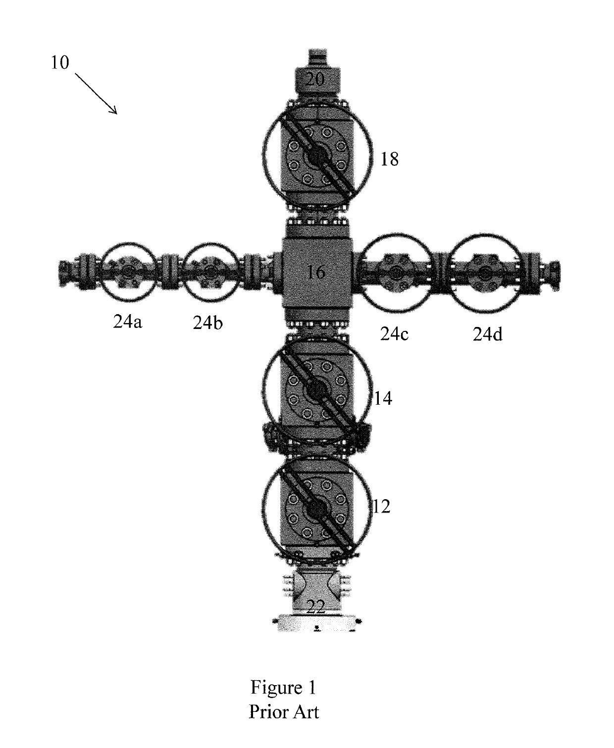
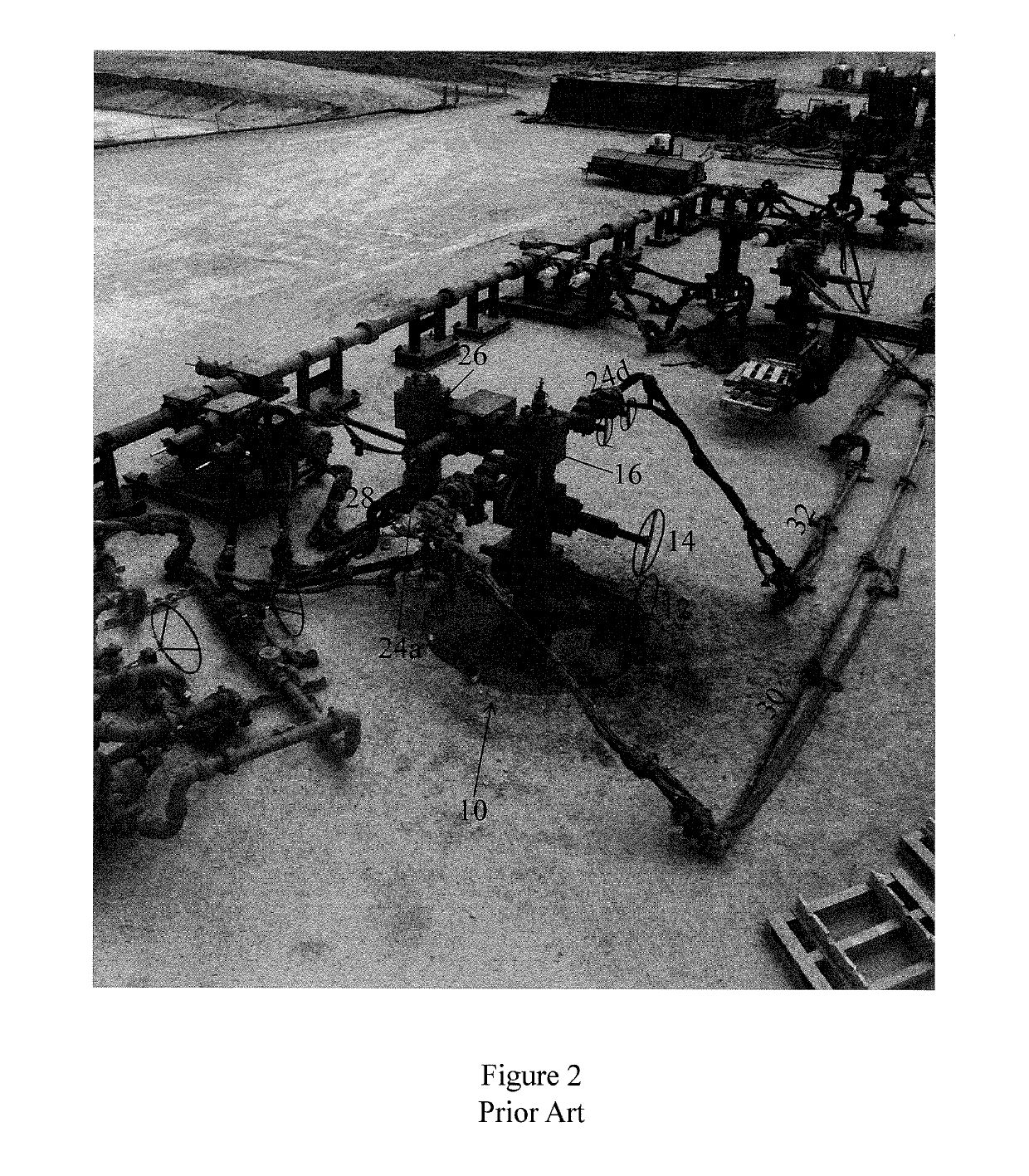
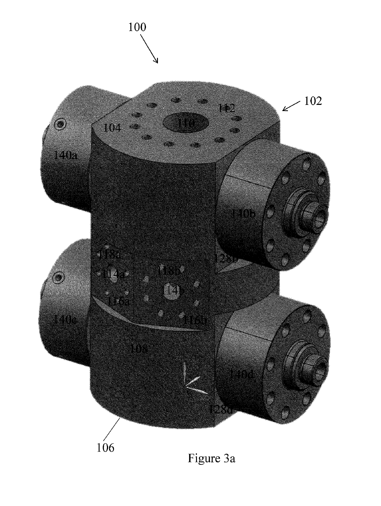
[0022]Embodiments of the present disclosure will now be described in detail with reference to the accompanying Figures. Like elements in the various figures may be denoted by like reference numerals for consistency. Further, in the following detailed description of embodiments of the present disclosure, numerous specific details are set forth in order to provide a more thorough understanding of the claimed subject matter. However, it will be apparent to one of ordinary skill in the art that the embodiments disclosed herein may be practiced without these specific details. In other instances, well-known features have not been described in detail to avoid unnecessarily complicating the description. Additionally, it will be apparent to one of ordinary skill in the art that the scale of the elements presented in the accompanying Figures may vary without departing from the scope of the present disclosure.

[0023]As used herein, the term “coupled” or “coupled to” or “connected” or “connected...


PUM


Abstract

A connector block having a single piece body may be configured for use in a Christmas tree. The connector block may include an axial bore formed therethrough, one or more valve chambers, passing fully through the connector block and intersecting the axial bore, one or more frac bores, extending from an outer surface of the connector block to the axial bore; and, one or more wing bores, extending from the outer surface of the connector block to the axial bore.

Description

BACKGROUND[0001]Christmas trees are assemblies of valves and other components used at well sites to control the flow of oil or gas out of the well and the flow of other fluids, such as frac fluid into the well. A traditional Christmas tree is shown in FIG. 1. The Christmas tree 10 may include two gate valves 12, 14, a central connector 16, and a swab valve 18 having a common axial bore (not shown). An upper end of the swab valve 18 may terminate at a cap 20. A lower end of the lower gate valve 12 may terminate at a wellhead connector 22. Four wing valves 24a-24d may be connected to the central connector in a transverse direction. A frac inlet (26 in FIG. 2) may also be connected to the central connector 16.[0002]The Christmas tree 10 may have, for example, a height of approximately fourteen to fifteen feet, a width of approximately twelve to thirteen feet and a weight of approximately twenty-eight thousand pounds. An operator may have to use a lift or a platform to operate the wing ...

Claims


Application Information

Patent Timeline
IPC IPC(8): E21B33/068E21B34/02E21B43/26
CPCE21B33/068E21B34/02E21B43/26E21B33/03E21B43/2607
Inventor COOK, JAMES
Owner FMC TECH INC
Learn More