
Removably mountable umbrella

a technology of umbrellas and brackets, applied in the field of umbrellas, can solve problems such as typical umbrellas

Inactive Publication Date: 2019-06-13
DETWEILER JOHN F +1
View PDF24 Cites 0 Cited by
  • Summary
  • Abstract
  • Description
  • Claims
  • Application Information

AI Technical Summary

Benefits of technology

The present invention offers an umbrella system that can be easily attached to almost any reasonably flat surface. This is achieved through a shaft, an umbrella canopy, a handle, an upper suction cup, and a lower suction cup. The handle has an upper and lower projection, with the upper and lower suction cups attached to the respective projections. The upper suction cup is attached to the upper projection while the lower suction cup is attached to the lower projection. A method for supporting the umbrella on a flat surface is also provided, involving adhering the upper and lower suction cups to the flat surface via suction.

Problems solved by technology

Nonetheless, despite their widespread usage, typical umbrellas suffer from several disadvantages.

Method used


Image

  • Removably mountable umbrella
  • Removably mountable umbrella
  • Removably mountable umbrella

Examples


Embodiment Construction

[0012]The present invention will be described with reference to illustrative embodiments. For this reason, numerous modifications can be made to these embodiments and the results will still come within the scope of the invention. No limitations with respect to the specific embodiments described herein are intended or should be inferred.

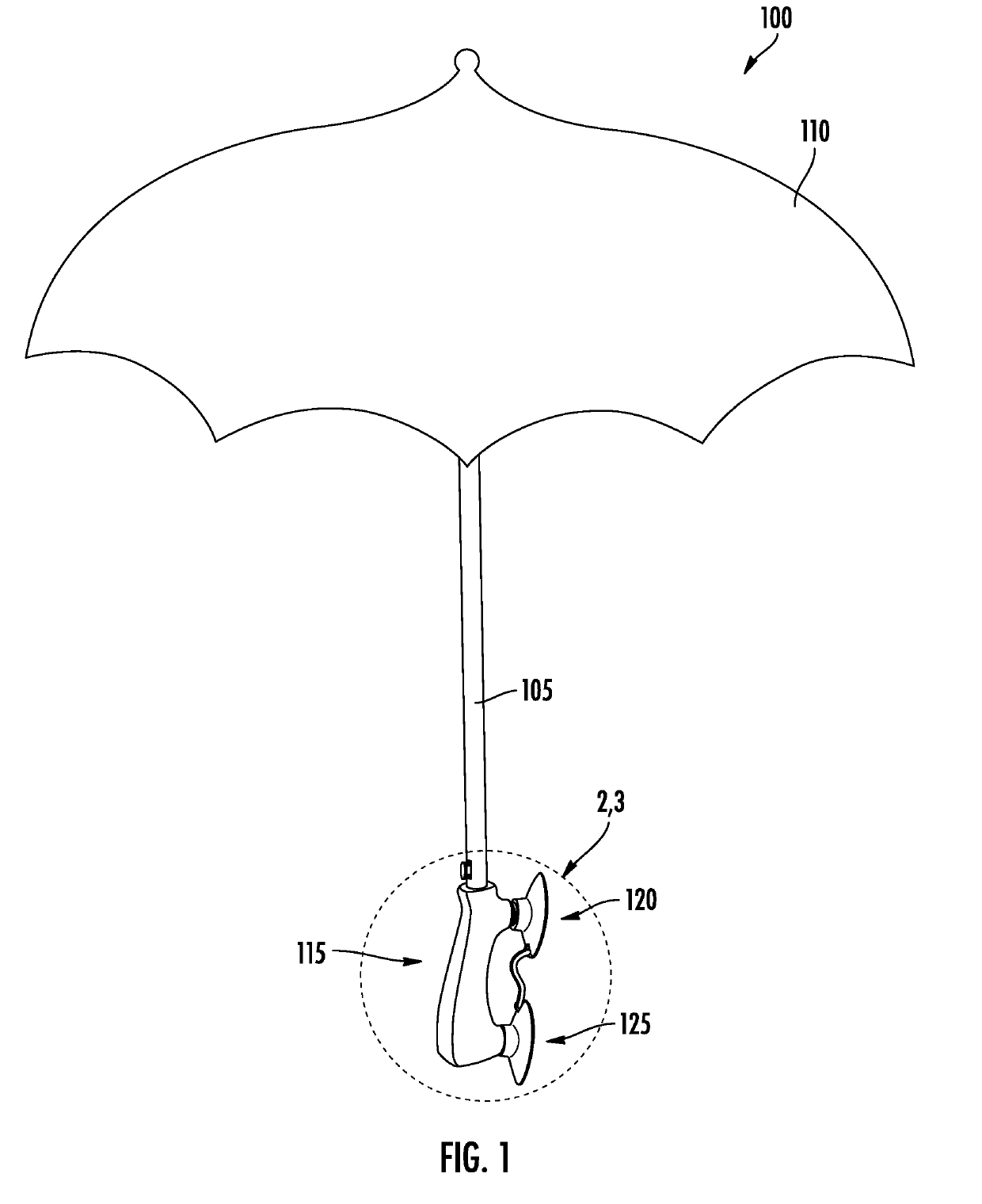
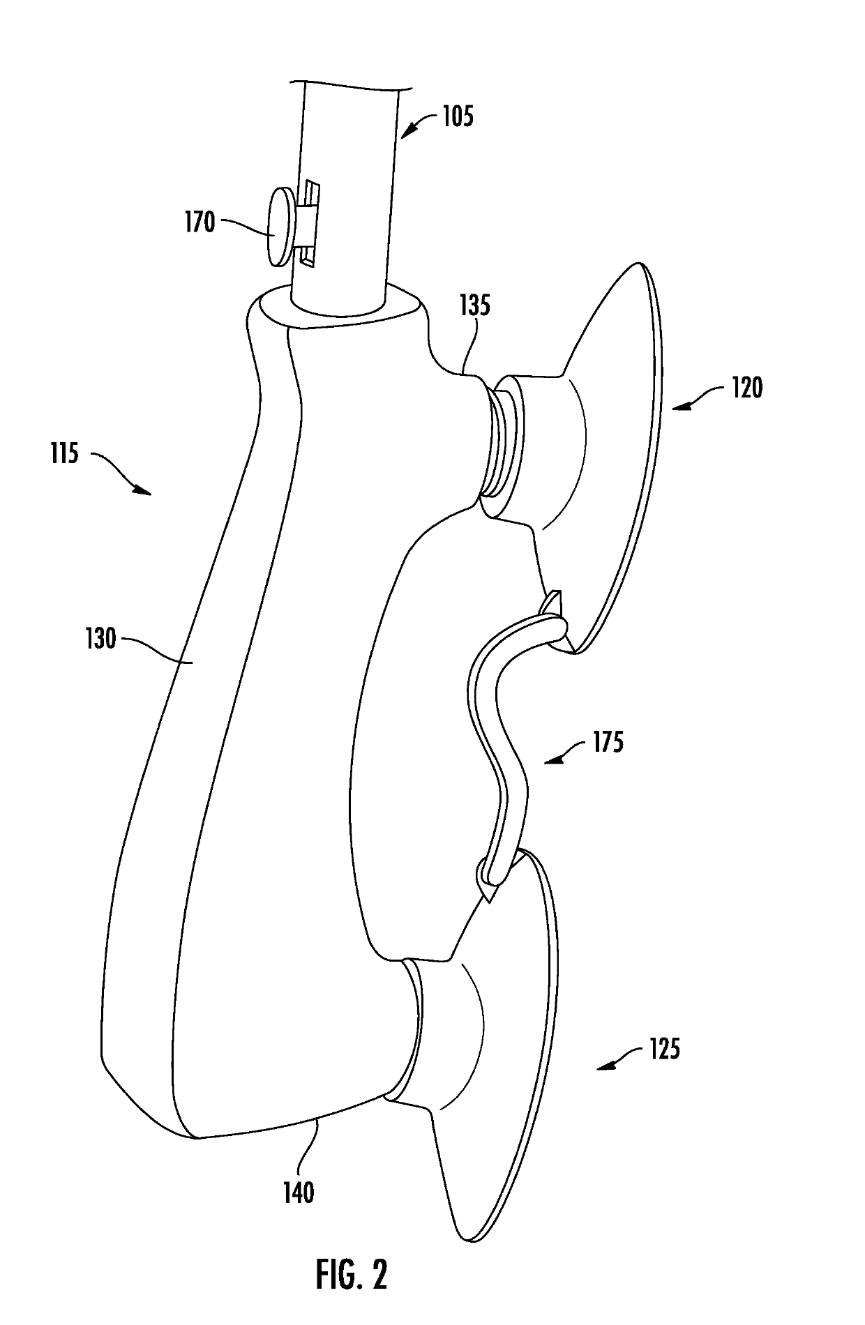
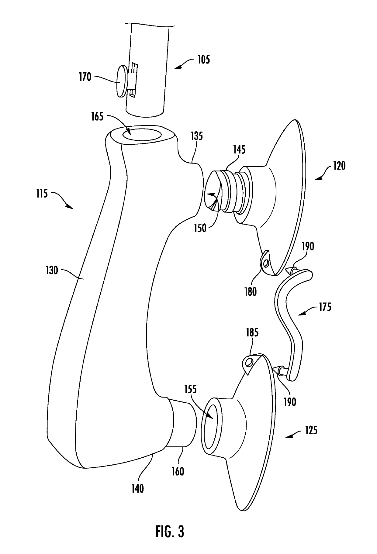
[0013]FIG. 1 shows a perspective view of an illustrative apparatus 100, which includes features of the claimed invention. The apparatus 100 comprises a shaft 105, an umbrella canopy 110, a handle 115, an upper suction cup 120, and a lower suction cup 125. The umbrella canopy 110 is attached to one end of the shaft 105, while the handle 115 is attached to another end of the shaft 105. At the same time, the upper and the lower suction cups 120, 125 are attached to the handle 115. Configured in this manner, the apparatus 100 may serve as an umbrella that is removably mountable to almost any flat surface. The apparatus 100 may, for example, be mounted to ...


PUM


Abstract

An apparatus including a shaft, an umbrella canopy, a handle, an upper suction cup, and a lower suction cup is described. The umbrella canopy and the handle are attached to the shaft. The handle includes a body, an upper projection, and a lower projection. The upper projection and the lower projection project from the body in the same direction and are in spaced relation to one another. The upper suction cup is attached to the upper projection, while the lower suction cup is attached to the lower projection. The apparatus may serve as a removably mountable umbrella.

Description

FIELD OF THE INVENTION[0001]The present invention relates generally to umbrellas, and, more particularly, to removably mountable umbrellas.BACKGROUND OF THE INVENTION[0002]An umbrella typically includes a folding canopy supported by wooden or metal ribs mounted on a wooden, metal, or plastic shaft. It may be used to protect a person from rain or sunlight.[0003]Nonetheless, despite their widespread usage, typical umbrellas suffer from several disadvantages. A user of an ordinary umbrella may, for example, be required to continuously hold the umbrella during its use, leaving only one hand free to perform other tasks. When loading packages into an automobile, for example, a user with a typical umbrella must use one hand to hold the umbrella while performing the loading with only the remaining hand.[0004]There is, as a result, a need for improved umbrella designs that allow an umbrella to be supported independently of a user so that the user is free to perform tasks with both hands.SUMM...

Claims


Application Information

Patent Timeline
Patent Type & Authority Applications(United States)
IPC IPC(8): A45B9/02A47G25/12A45B11/00
CPCA45B9/02A47G25/12A45B11/00A45B2023/0025A45B2200/109B60R2011/0056B60R11/00B60R2011/004
Inventor DETWEILER, JOHN F.DETWEILER, KRISTY L.
Owner DETWEILER JOHN F
Learn More