
Lavatory Enclosure-to-Toilet Device with Replaceable Cartridge For Hygienic Support of Lowered Slacks

Active Publication Date: 2019-06-13
GIVING CENT
View PDF0 Cites 0 Cited by
  • Summary
  • Abstract
  • Description
  • Claims
  • Application Information

AI Technical Summary

Benefits of technology

The invention is a mechanical device that can be used in public restroom stalls to protect the user's clothes from the floor. The device has an arm that can be raised and lowered to support the user's slacks or skirt while using the toilet. The arm is attached to a housing that can be secured to the stall or to a wall. The device is easy to use and can be easily stored when not needed. It prevents the user's clothes from touching the floor, which can be unclean due to foot traffic or urination. The arm has a stop to prevent excessive movement from the stowed position to the deployed position, and the arm can have a slidable sleeve to make it easier to raise and lower. The invention provides a quick and effective means to protect the user's clothes while using the toilet.

Problems solved by technology

The floor may also have become soiled from a previous user of the stall having urinated while standing.
In addition, the knob that is used to actuate the latch of the stall door may be wired to the catch, so that if a user seeks to egress from the stall without first raising the slacks valet mechanism, which could result in damage to the device and possibly prevent the stall door from opening fully, the catch will be tripped to cause the device's automatic retraction.

Method used


Image

  • Lavatory Enclosure-to-Toilet Device with Replaceable Cartridge For Hygienic Support of Lowered Slacks
  • Lavatory Enclosure-to-Toilet Device with Replaceable Cartridge For Hygienic Support of Lowered Slacks
  • Lavatory Enclosure-to-Toilet Device with Replaceable Cartridge For Hygienic Support of Lowered Slacks

Examples


first embodiment

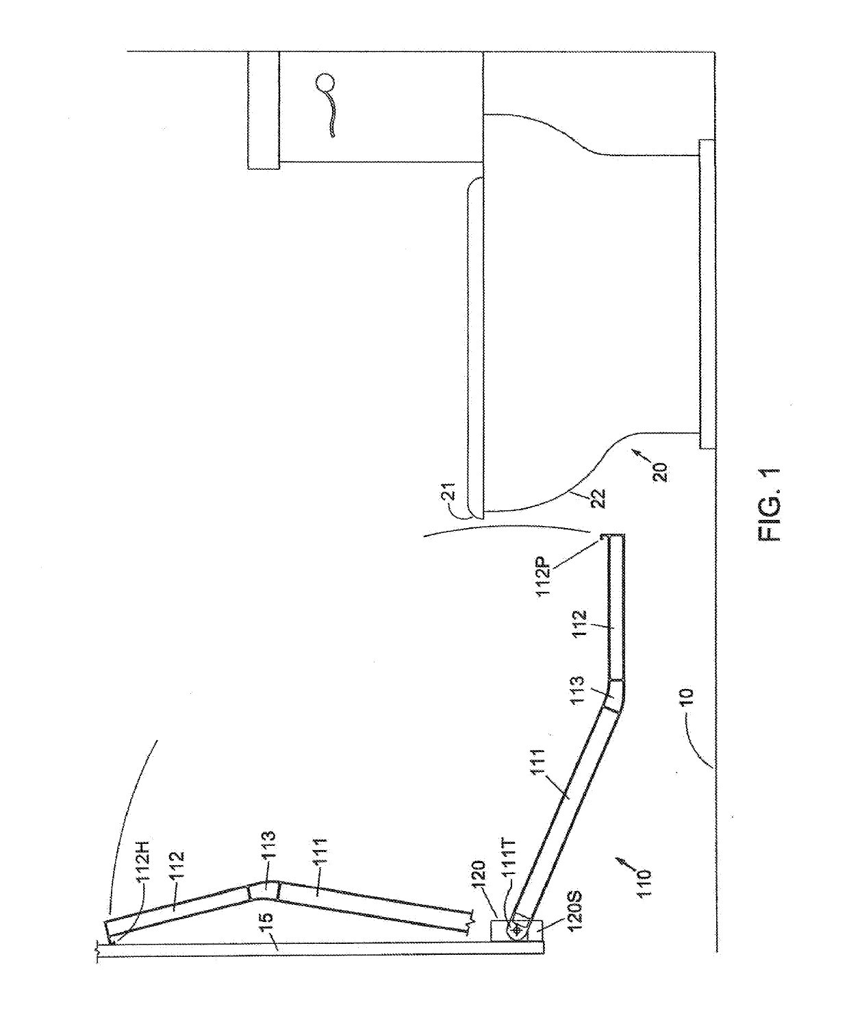
[0062]FIG. 1 shows the present invention—slacks valet mechanism 110. The slacks valet mechanism 110 may be mounted to the door of a lavatory stall, and could also be mounted to a wall of the lavatory where it may function in a similar manner. The slacks valet 110 is a basic embodiment, which principally overcomes the problems encountered when attempting to provide protection to a user's slacks when the user seeks to utilize the toilet in a public lavatory stall.

[0063]There are a number of problems that each of the mechanisms herein must overcome in order to be functional in a deployed position, while lending itself to quick and convenient stowage in a minimally invasive volume, because such lavatory stalls are generally very compact. The stowed mechanism must not impinge upon the stall door's cycle of rotation from its closed position to its full open position. While in the open position, the door may remain slightly displaced from the wall of the stall by contact of a combination s...

second embodiment

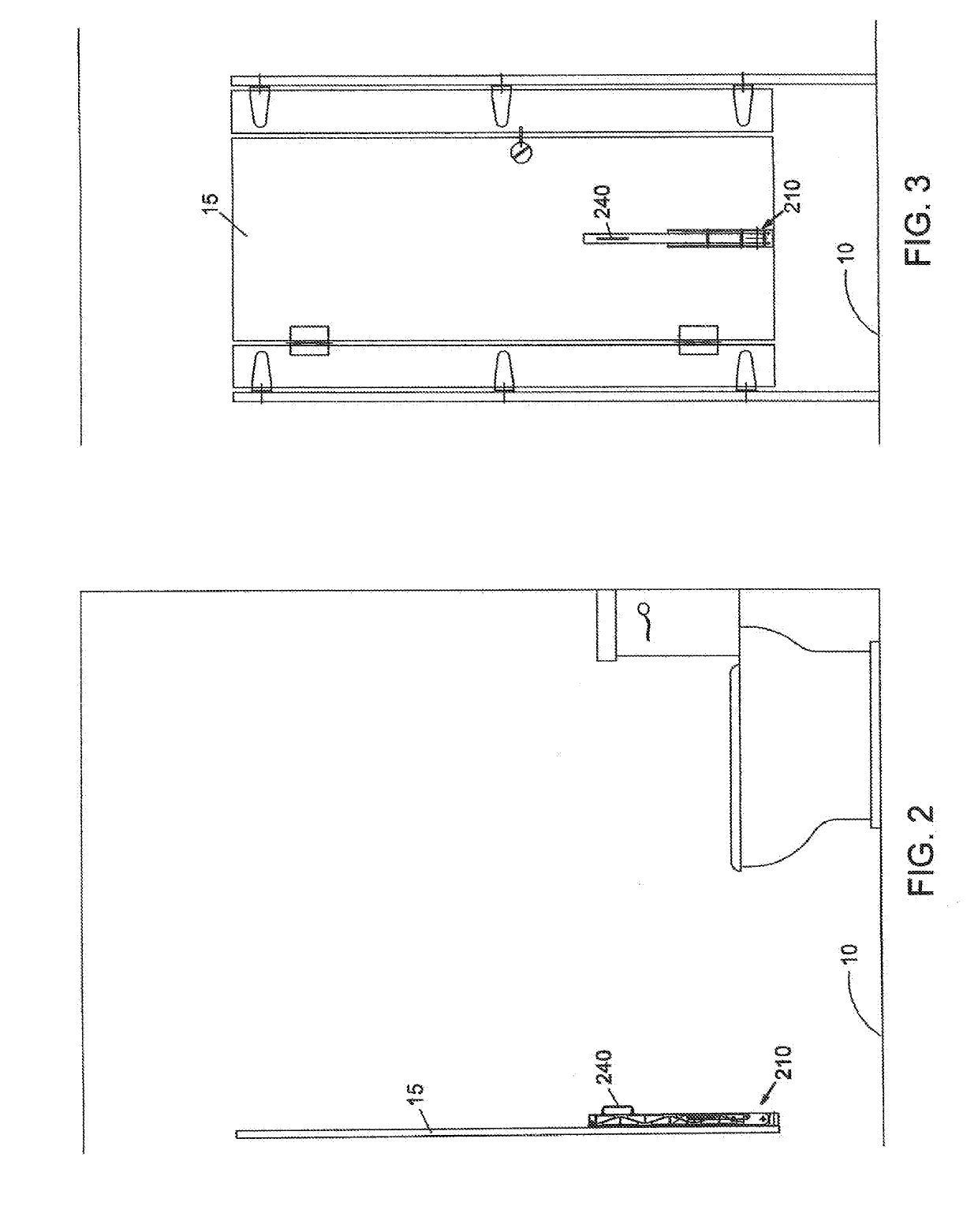
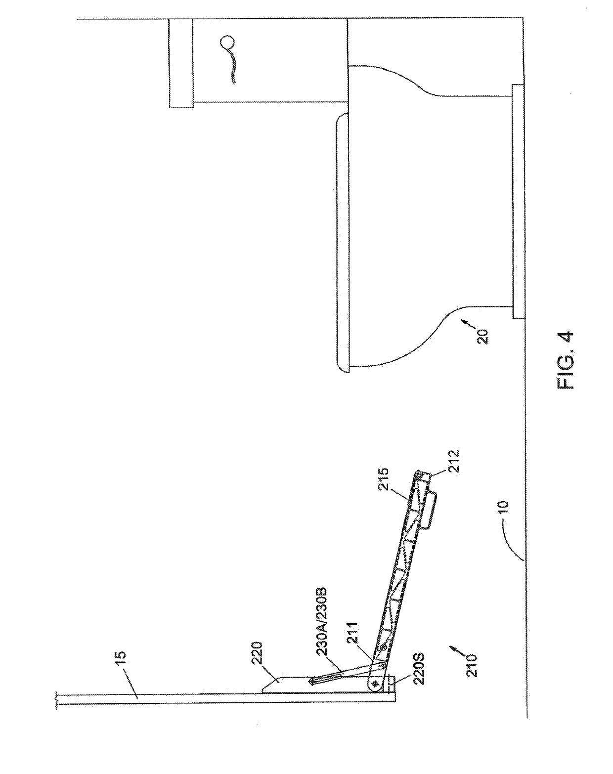
[0069]So, while the basic slacks valet mechanism 110 may be functional in terms of satisfying the requirements for stowage and deployment, the above factors create a tension between making modifications to it for more elegant satisfaction of the initially stated problems, in order to provide a higher level of utility for the user within the lavatory stall. Therefore, greater utility may be provided by the slacks valet mechanism of the current invention, which is shown in the stowed position in FIGS. 2 and 3.

[0070]As seen in FIG. 3, the slacks valet mechanism 210 may be positioned on the lower portion of the stall door 15, and, as mentioned earlier, it may generally be centered laterally on the door. However, it should be noted that, during the installation of the mechanism onto the stall door 15, the primary concern is not that it be centered on the door, but rather that it be mounted so that it extends to be generally centered upon the toilet itself, which may be slightly off cente...

third embodiment

[0078]Other utility may be provided by the slacks valet mechanism of the current invention, which is shown in the extended position in FIG. 6. As seen in FIG. 6, the slacks valet mechanism 310 may also be positioned on the lower portion of the stall door 15, and may be secured thereto using fasteners that may attach the housing 320 to the stall door. Slacks valet mechanism 310 may have a first arm 311 that may be pivotally attached to the housing 320, which is seen in the enlarged view of FIG. 7. Instead of the first arm 311 being pivotally attached directly to the walls of the housing 320, it may instead be pivotally mounted to a pin 315 that may be pivotally mounted to the bottom of housing 320. First arm 311 may be formed to have a channel as its cross-sectional shape, which may have a first end closed off by an end wall 311EW (FIG. 8), and from which may extent a tongue 311T. The tongue 311T may be pivotally received in a clevis 315C on pin 315, using, for example, a bolt and a ...


PUM


Abstract

A slacks valet mechanism, to prevent the slacks of a user of a lavatory stall toilet from becoming soiled by preventing its contact with the floor, includes an arm coupled to the stall door / wall, being movable between stowed and deployed positions. The stowed arm is proximate to the lavatory door, and the deployed arm has a portion proximate to the toilet, to thereon receive the lowered slacks to prevent soiling. A replaceable cartridge is releasably securable to the arm, and includes first and second reels, and a hygienic tape wound upon the first reel with an end fixedly secured to the second reel. The device incrementally advances an outermost portion of the hygienic tape on the first reel onto the second reel, for each cycle of the arm between the deployed and stowed positions, thereby exposing an unused tape portion on the arm for hygienic slacks support.

Description

CROSS REFERENCE TO RELATED APPLICATIONS[0001]This application is a continuation in part of U.S. patent application Ser. No. 13 / 794,454, filed on Mar. 11, 2013, which claims priority on U.S. Provisional Application Ser. No. 61 / 685,119, filed on Mar. 12, 2012, titled “Lavatory Stall Slack Valet,” and on U.S. Provisional Application Ser. No. 61 / 688,320, filed on May 10, 2012, titled “Slack Valet Mechanism For A Lavatory,” with the disclosures of each being incorporated herein by reference.FIELD OF THE INVENTION[0002]This invention relates to improvements in the use of public restroom toilets, and more particularly to a means of support that may be installed upon the stall door or lavatory wall to be selectively deployed to preserve the cleanliness of a user's slacks, by preventing contact with the floor, when utilizing the toilet therein.BACKGROUND OF THE INVENTION[0003]Many people find using a public restroom to be an unpleasant experience, particularly with respect to the potential f...

Claims


Application Information

Patent Timeline
IPC IPC(8): A47K17/02F16M13/02
CPCA47K17/02F16M13/02A47D5/006A47K13/00F16M11/10F16M11/2021F16M11/24F16M11/38F16M11/42F16M2200/028F16M2200/044
Inventor BONGIORNO, JAMES
Owner GIVING CENT
Learn More