
Stemless prosthesis anchor components, methods, and kits

a technology of stemless prosthesis and components, applied in the field of stemless prosthesis anchor components of joint prosthesis, can solve the problems of limiting the distance between the humerus and the glenoid, and inset positioning can compromise the integrity of the fixation into the humerus, so as to improve the ability of the surgeon to position, minimize the risk of dislocation of the shoulder joint or acromion fracture, and improve the soft tissue tension

Active Publication Date: 2019-06-13
HOWMEDICA OSTEONICS CORP
View PDF0 Cites 21 Cited by
  • Summary
  • Abstract
  • Description
  • Claims
  • Application Information

AI Technical Summary

Benefits of technology

The technical effect of this patent is to create new stemless shoulder assemblies that improve the surgery process by allowing the humerus to be placed in different ways after inserting its anchor into the bone marrow canal. This increases the stability of the patient's shoulder joint and reduces the chances of complications like dislocation or fracture. These assemblies are also designed to protect the bone during insertion and ensure strong attachment over time.

Problems solved by technology

The technical problem addressed by this patent relates to improving the design of prosthetic joints used to replace damaged skeletal joints like shoulder joints. Specifically, there is a need to address issues related to conventional methods of connecting humoral components (which face the glenoid) to stemless humeral anchors, while also ensuring proper attachment without adding excessive thickness to the overall assembly.

Method used


Image

  • Stemless prosthesis anchor components, methods, and kits
  • Stemless prosthesis anchor components, methods, and kits
  • Stemless prosthesis anchor components, methods, and kits

Examples


Embodiment Construction

[0042]While the present description sets forth specific details of various embodiments, it will be appreciated that the description is illustrative only and should not be construed in any way as limiting. Furthermore, various applications of such embodiments and modifications thereto, which may occur to those who are skilled in the art, are also encompassed by the general concepts described herein. Each and every feature described herein, and each and every combination of two or more of such features, is included within the scope of the present invention provided that the features included in such a combination are not mutually inconsistent.

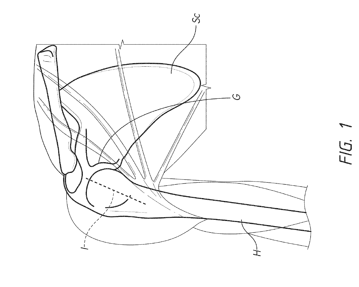
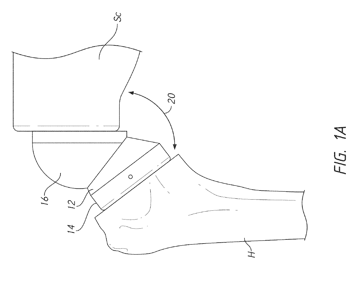
[0043]This application is directed to shoulder implants that provide greater control of the soft tissue tension around the joint following implantation. The improvements herein enable a patient to have an appropriate level of tension in the soft tissue to provide good range of motion while reducing the risk of dislocation of the shoulder joint or...


PUM


Abstract

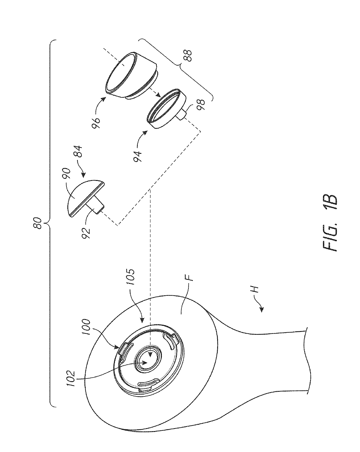
A prosthesis assembly is provided that includes a base member that has a helical structure and a cylindrical member opposite the helical structure. The cylindrical member is configured for direct connection with a reverse insert of a reverse shoulder assembly. The cylindrical member is configured for direct connection with a reverse insert spacer in some embodiments. The reverse insert can be inserted into a space defined at least in part by a wall of the cylindrical member and an inferior wall of the of the base member. The helical structure extends between a first end and a second end. The base member also can include one or more pathways. The pathway(s) is accessible from the second end and is directed toward the first end through the helical structure. The pathway is located inward of an outer periphery of the helical structure, e.g., adjacent to an inner periphery of the helical structure. The pathway extends in a space between successive portions of the helical structure. The prosthesis assembly can include a locking device that has a support member and an arm that projects away from the support member. The arm is configured to be disposed in the pathway when the support member is disposed adjacent to the second end of the base member. The arm is disposed through bone in the space between successive portions of the helical structure when the prosthesis assembly is implanted.

Description


Claims


Application Information

Patent Timeline
Owner HOWMEDICA OSTEONICS CORP
Learn More