Container carrier with flexible flange

a container carrier and flexible technology, applied in the direction of transportation and packaging, rigid containers, other domestic articles, etc., can solve the problems of compromising the integrity of the product and causing frustration

Active Publication Date: 2019-08-08
OREGON PRECISION IND INC DBA PAKTECH
View PDF10 Cites 0 Cited by
  • Summary
  • Abstract
  • Description
  • Claims
  • Application Information

AI Technical Summary

Benefits of technology

[0003]To address the above issues, a container carrier and manufacturing method for a container carrier are disclosed herein. According to a first aspect, a container carrier for securing together and carrying multiple containers is provided comprising an integrally molded body that includes a plurality of annular structures. Each annular structure is connected by a bridge to at least one adjacent annular structure of the plurality of annular structures. Each annular structure includes a side wall formed of side wall portions and a top surface connecting the side wall portions. The side wall portions are separated by side wall voids formed in the side wall. A respective flange is positioned proximate a bottom end of each side wall void. The flanges of each annular structure are collectively configured to releasably engage a corresponding container of the multiple containers. To this end, the flanges project inwardly and orient upwardly at an angle and are configured to flex when accepting or releasing a corresponding container of the multiple containers. The top surface connecting the side wall portions of each annular structure includes notched voids continuous with respective side wall voids. As such, the flanges positioned proximate the bottom ends of each side wall void may be accommodated by the notched voids in the top surface of a second, same-shaped container carrier when stacked. The flanges are configured to have a perimeter profile as viewed from above that is smaller and nests within a perimeter profile as viewed from above of the notched voids in the top surface. Potential advantages of this configuration are that the flanges do not inhibit efficient stacking of the container carriers and that multiple containers may be securely transported in one carrier yet individually removed with ease from the container carrier.
[0004]In this aspect, each side wall portion has a respective upper side wall segment and a respective lower side wall segment. The upper side wall segment has a reduced diameter relative to the lower side wall segment of the side wall portion. The upper and lower side wall segments are configured to join at a horizontally extending ledge that spans a difference between the respective diameters in the upper and lower side wall segments. A potential advantage of this configuration is that the container carriers are shaped to nest together when stacked, which allows for more efficient packing and shipping of container carriers in comparison to currently available solutions.
[0005]In this aspect, the bottom portion of the lower side wall segment is shaped to have an inner diameter that is larger than an outer diameter of the upper side wall and smaller than an outer diameter of the ledge. As such, the bottom portion of the lower side wall segment will rest upon the ledge of a second, same-shaped container carrier when stacked. A potential advantage of this configuration is that the container carriers nest snuggly together when stacked to minimize lateral shifting of the stock while in shipping containers, thereby reducing the potential of damaging the container carriers during transit.

Problems solved by technology

With current solutions, users often experience difficulty releasing a container from a container carrier, which may result in frustration and compromise the integrity of the product.

Method used


Image

  • Container carrier with flexible flange
  • Container carrier with flexible flange
  • Container carrier with flexible flange

Examples


Embodiment Construction

[0034]Selected embodiments of the present disclosure will now be described with reference to the accompanying drawings. It will be apparent to those skilled in the art from this disclosure that the following descriptions of the embodiments of the disclosure are provided for illustration only and not for the purpose of limiting the disclosure as defined by the appended claims and their equivalents.

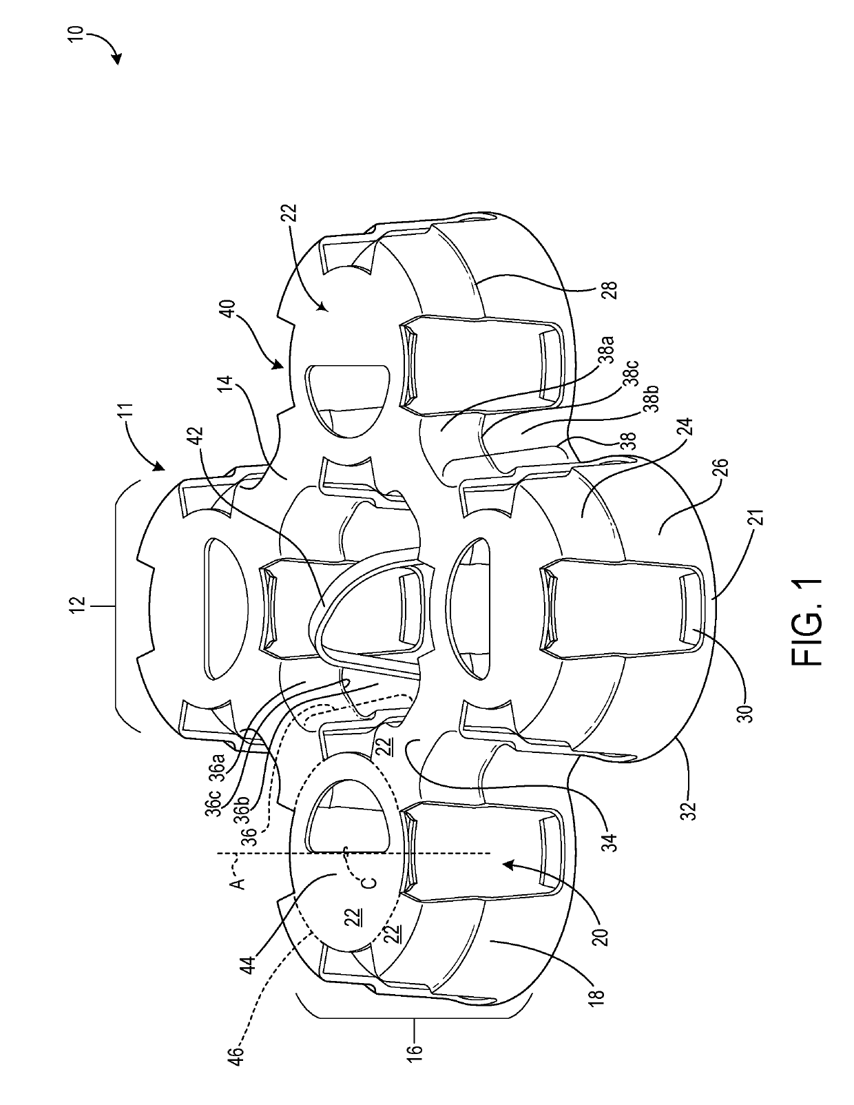
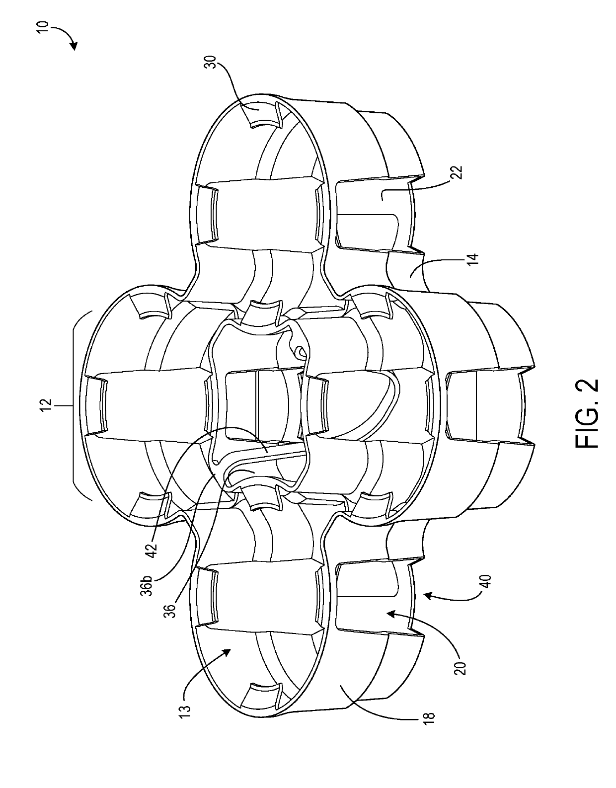
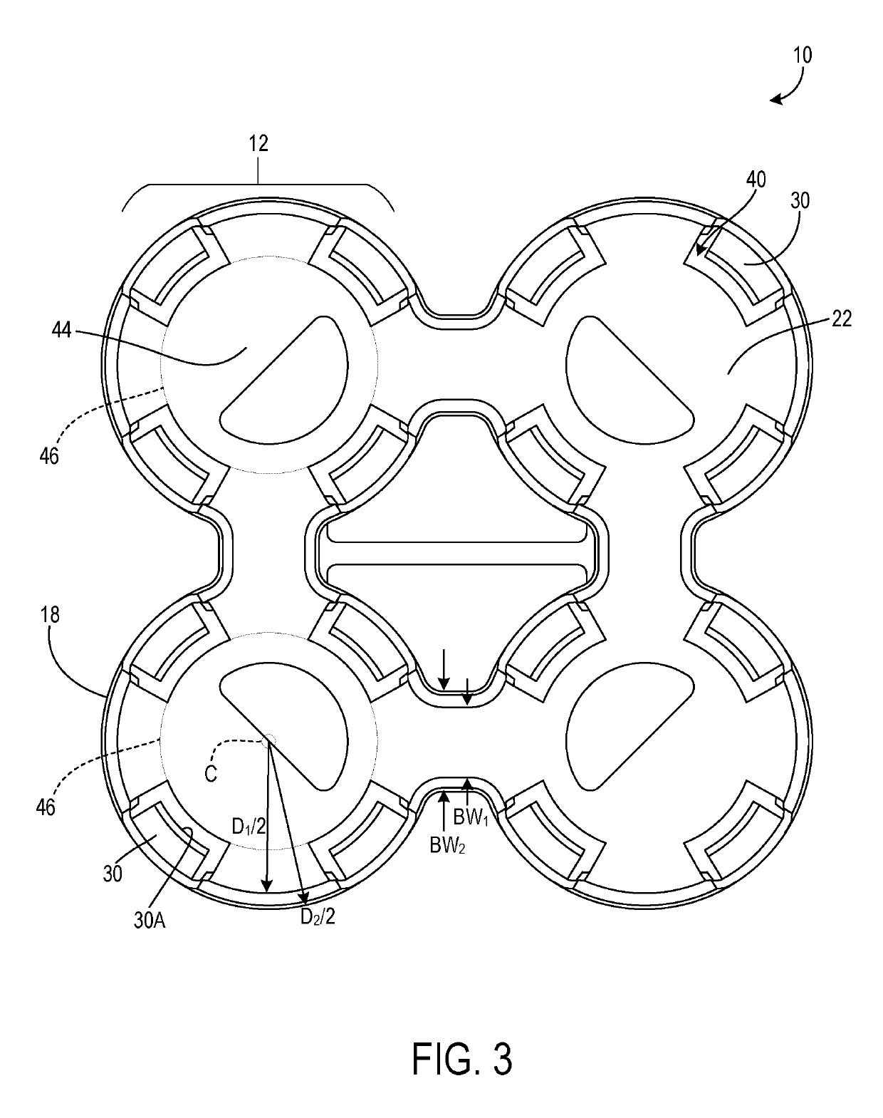
[0035]Turning to the figures, FIG. 1 illustrates one embodiment of a container carrier 10 configured to secure together and carry multiple containers at one time. The body 11 of the container carrier 10 may be integrally molded and may include at least a plurality of annular structures 12. Each annular structure 12 may be connected to at least one adjacent annular structure 12 by a bridge 14.

[0036]The annular structures 12 may each comprise a side wall 16 formed by side wall portions 18 that are separated by side wall voids 20 formed in the side wall 16. A top surface 22 may connect the sid...


PUM

PropertyMeasurementUnit
angle of inclinationaaaaaaaaaa

Abstract

A container carrier and manufacturing method for a container carrier are provided. The container carrier includes an integrally molded body with a plurality of annular structures connected by a bridges. The annular structures each include a side wall formed of side wall portions separated by side wall voids and a top surface. Flanges are positioned at the bottom of each side wall void to collectively engage the containers. The flanges are configured to project inwardly and orient upwardly at an angle so as to flex when accepting or releasing a container. The top surfaces of the annular structures include notched voids continuous with respective side wall voids such that the flanges positioned at the bottoms of the side wall voids are accommodated by the notched voids in the top surface of a second, same-shaped container carrier when stacked.

Description

CROSS-REFERENCE TO RELATED APPLICATIONS[0001]This application is a continuation of U.S. patent application Ser. No. 15 / 449,831, filed Mar. 3, 2017 and entitled CONTAINER CARRIER WITH FLEXIBLE FLANGE, the disclosure of which is hereby incorporated by reference in its entirety for all purposes.BACKGROUND[0002]Container carriers are used in retail environments to secure a group of containers so that they may be grasped and carried as a single unit. This configuration is advantageous to a user who desires to transport several containers at once, such as cans or bottles of beverages. Heavier products, such as liquids, may require three-dimensional container carriers to support their weight. Additionally, products with caps, such as bottles, may need a taller container carrier to accommodate the caps. Such container carriers must engage the products securely but also allow them to be easily released by a user. With current solutions, users often experience difficulty releasing a container...

Claims


Application Information

Patent Timeline
Patent Type & Authority Applications(United States)
IPC IPC(8): B65D71/50B29C67/24B65D21/02B65D71/00
CPCB65D71/50B29C67/24B65D21/02B65D71/00B65D21/0233B29K2023/065B29L2031/7178B29K2105/26B65D21/0231B65D21/0209B65D21/0235B65D71/70B65D2571/00895B65D71/0003
Inventor BORG, ZAKARY JAMESMELLOR, JR., RONALD LEE
Owner OREGON PRECISION IND INC DBA PAKTECH
Why Eureka
Try Eureka