
Valve position indicator with leds

Active Publication Date: 2019-08-15
BRAY INT
View PDF0 Cites 0 Cited by
  • Summary
  • Abstract
  • Description
  • Claims
  • Application Information

AI Technical Summary

Benefits of technology

The disclosure is about a valve with a position indicator that uses LED lights to show the valve's status. The indicator has a cover and a surface with a rim, and the LED lights are arranged along the rim. The valve also has a sensor that communicates with the actuator and the LED lights to inform them about the position of the valve. The use of LED lights makes the valve position indicator easier to read and can be seen from a distance. The technical effect of this invention is to provide a more convenient and easily visible valve position indicator that can be easily read from a distance.

Problems solved by technology

It may be difficult to know the position of the valve from the location of the actuator (for example, the hand wheel or power actuator).

Method used


Image

  • Valve position indicator with leds
  • Valve position indicator with leds
  • Valve position indicator with leds

Examples


Embodiment Construction

)

[0024]The description that follows includes exemplary apparatus, methods, techniques, and instruction sequences that embody techniques of the inventive subject matter. However, it is understood that the described embodiments may be practiced without these specific details.

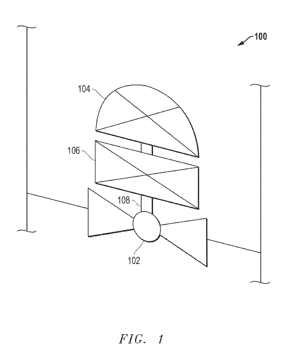
[0025]FIG. 1 depicts a schematic view of a piping system 100 having a valve 102 with a valve position indicator 104 according to an embodiment. The piping system 100 may be any suitable piping system that requires the control of flow within the piping system 100. The valve 102 may have an actuator 106 configured to move the valve 102 between an open and a closed position. The actuator 106 may be any suitable actuator including, but not limited to, a pneumatic actuator, a hydraulic actuator, an electric actuator, a hand wheel, a lever, and the like. The actuator 106 may have an actuator shaft 108 configured to manipulate the valve position indicator 104 as the valve 102 moves between the open and closed position as...


PUM


Abstract

The disclosure relates to a valve having: an actuator; a valve position indicator coupled to the actuator, wherein the valve position indicator includes: an indicator cover mounted over an indicator mounting surface, wherein the indicator mounting surface has a rim; a plurality of LED lights arranged on the indicator mounting surface, wherein the LED lights are bordering the rim of the indicator cover; and a sensor in communicative connection with the actuator and the plurality of LED lights, wherein the sensor is configured to communicate the position of the valve to the plurality of LED lights

Description

BACKGROUND[0001]Valves may be used in a number of applications to control the flow of fluids through piping systems. There are several different types of valves used for controlling flow such as ball valves, gate valves, butterfly valves, needle valves, check valves, and the like. Ball valves, butterfly valves, needle valves and gate valves may be actuated with an actuator, a manual hand wheel, or manual lever between the open and closed position. It may be difficult to know the position of the valve from the location of the actuator (for example, the hand wheel or power actuator). Therefore a need exists for an improved valve position indicator for use with valves. There is a further need for a valve indicator that better communicates the position of the valve through the display.BRIEF SUMMARY[0002]The disclosure relates to a valve having: an actuator; a valve position indicator coupled to the actuator, wherein the valve position indicator includes: an indicator cover mounted over ...

Claims


Application Information

Patent Timeline
IPC IPC(8): F16K37/00
CPCF16K37/0041F16K37/0058
Inventor BROWN, CRAIGWALKER, DANSCHMIDT, JAMES F.
Owner BRAY INT
Features
  • Generate Ideas
  • Intellectual Property
  • Life Sciences
  • Materials
  • Tech Scout
  • Unparalleled Data Quality
  • Higher Quality Content
  • 60% Fewer Hallucinations
Learn More