

Rumble strip following for automated vehicle steering
a technology of automated vehicle steering and following system, which is applied in vehicle position/course/altitude control, process and machine control, instruments, etc., can solve the problem that the lane markings used for automated operation of host-vehicle may not be detectable by a camera on the hos
- Summary
- Abstract
- Description
- Claims
- Application Information
AI Technical Summary
Benefits of technology
Problems solved by technology
Method used
Image

Examples
Embodiment Construction
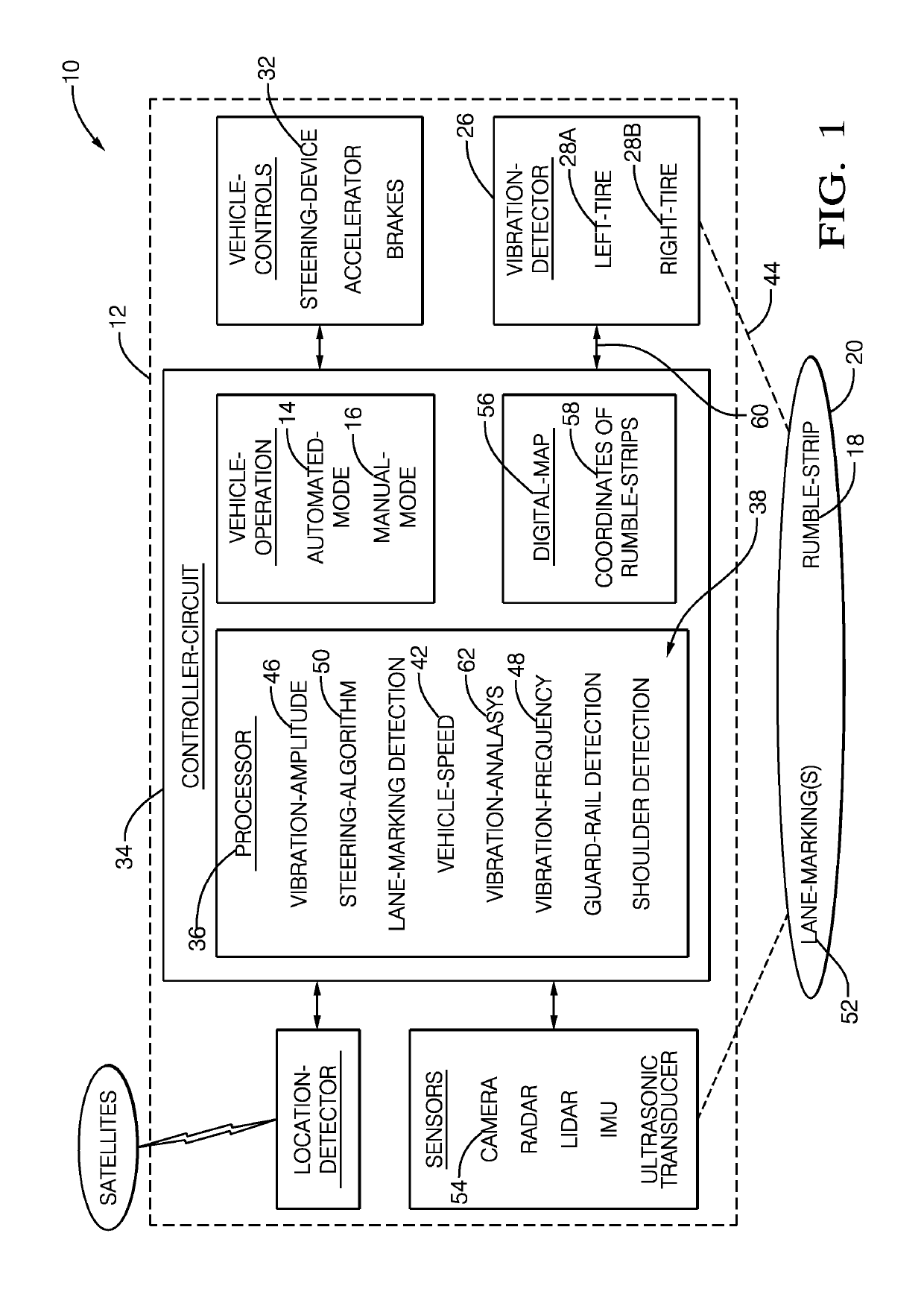
[0007]FIG. 1 illustrates a non-limiting example of a rumble-strip following system 10, hereafter referred to as the system 10. In general, the system 10 is for automated vehicle steering of a host-vehicle 12, however the system 10 is not limited to only steering the host-vehicle 12. The host-vehicle 12 may be characterized as an automated vehicle. As used herein, the term automated vehicle may apply to instances when the host-vehicle 12 is being operated in an automated-mode 14, i.e. a fully autonomous mode, where a human-operator (not shown) of the host-vehicle 12 may do little more than designate a destination to operate the host-vehicle 12. However, full automation is not a requirement. It is contemplated that the teachings presented herein are useful when the host-vehicle 12 is operated in a semi-automated-mode (a variation on the automated-mode 14) that controls the steering of the host-vehicle 12 while the accelerator and brakes are generally controlled by the operator. The ho...
PUM
 Abstract
Description
Claims
Application Information