Support assembly for engaging a small electronic device

a technology for supporting assemblies and electronic devices, which is applied in the direction of telephone set constructions, stand/trestles, beds, etc., can solve the problems of limited ability to engage the support assembly at a variety of attitudes or angles, and achieve the effect of achieving stability with minimal effort and simple and quick changes of configuration

Inactive Publication Date: 2019-09-05
SCHOLZ CHARLES W
View PDF0 Cites 0 Cited by
  • Summary
  • Abstract
  • Description
  • Claims
  • Application Information

AI Technical Summary

Benefits of technology

[0007]The support device disclosed is based on new and unique concept. Its use, instant viewing angle change, and easy pocket storage are the result of an electronic device and the support device combining to essentially form a unit. Current stands and support are generally of the following variety: (a) supports with which one object sits or leans against another (most static and adjustable phone stands), which allow only pre-defined viewing angles; (b) supports that have an adhesive surface to ‘cling” to electronic devices, making adjustments possible only by breaking the seal formed by the adhering material; or (c) supports that either grip or adhere to electronic devices and have flexible necks, which are too large for a pocket and often require considerable effort to adjust comfortably.
[0008]This support device has no pre-defined viewing angles (viewing angle can be changed to any angle whatsoever, between the upper and lower limits based on the size of the electronic device); does not adhere (not tacky or sticky) to the electronic device, which allows immediate change of angle when desired; and is typically about a centimeter or less in thickness (or in another range, about ⅛″ to ¾″ or ⅛″ to ⅜″) when prepared for storage or carrying in a shirt pocket. This is possible because the upper surface of the support device maintains its position with respect to the back of an electronic device by friction between the two, achieving stability with minimal effort. A change of angle requires only moving the support device up or down against the back of the electronic device. With no adhesion or other chemical grip, the singular design allows for simple and quick changes of configuration, both in angle and orientation.

Problems solved by technology

Prior art stands have a number of shortcomings, including the limited ability to provide proper angular viewing and limited ability for engaging the support assembly at a variety of attitudes or angles.

Method used


Image

  • Support assembly for engaging a small electronic device
  • Support assembly for engaging a small electronic device
  • Support assembly for engaging a small electronic device

Examples


Embodiment Construction

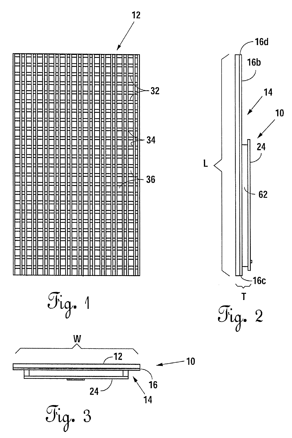
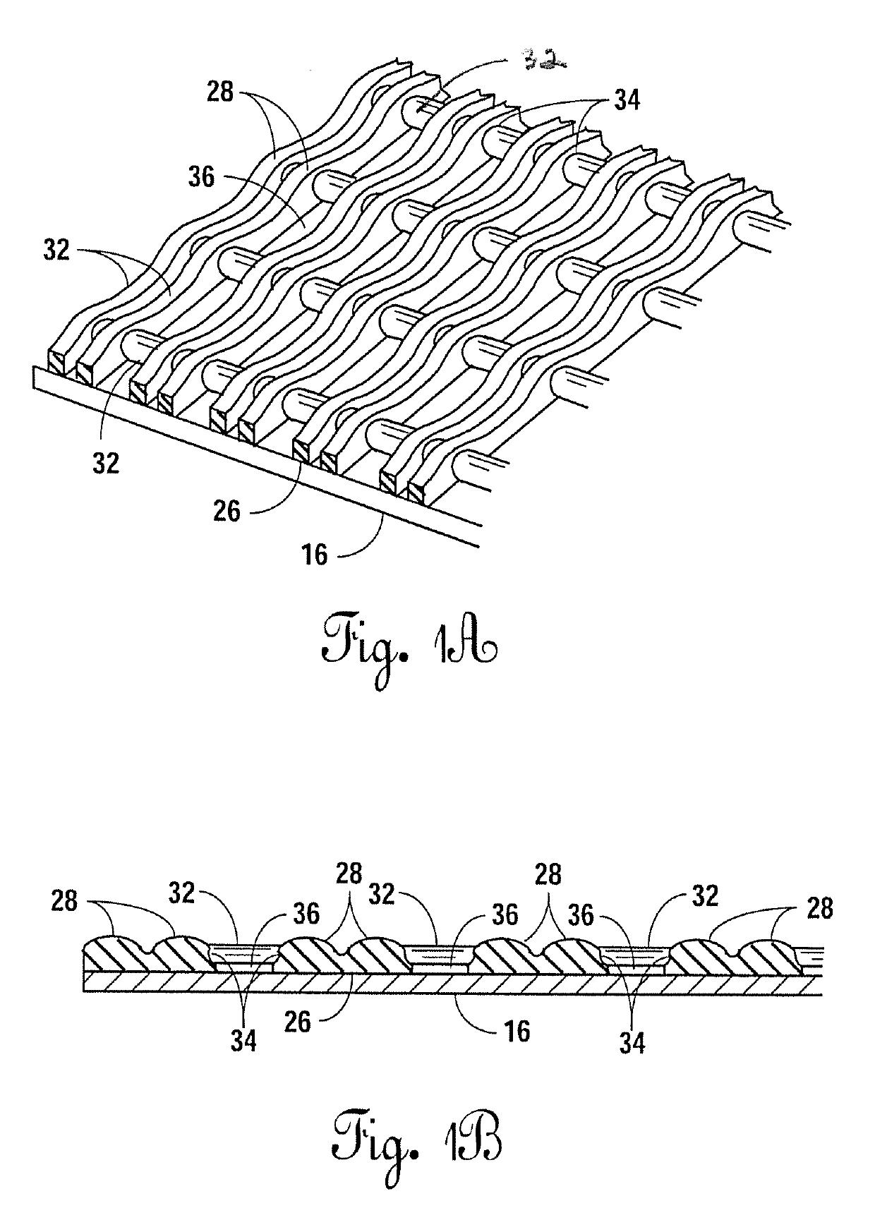
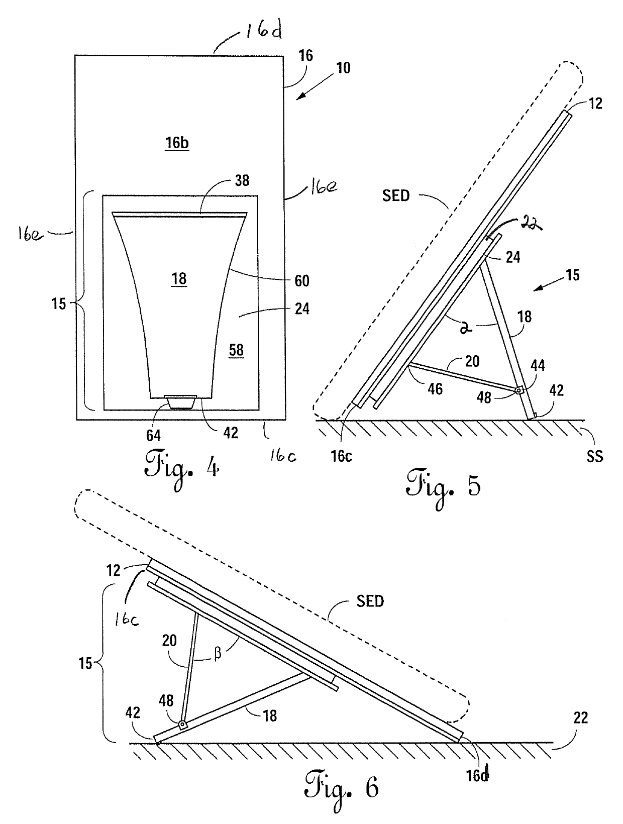
[0032]Applicant provides a small electronic device support assembly. The support assembly includes a stand having a base and a support leg assembly engaging the base. On the top face of the base is provided a soft, resilient, non-slip pad. The soft, resilient non-slip pad has multiple high points defining a top or upper surface, the multiple high points spaced apart from one another such that there are typically dozens or even hundreds of multiple high points for engaging the bottom surface of the electronic device. In other words, the pad, affixed to the base, does not have a smooth top surface, but instead defines multiple soft projections or raised points spaced apart from each other which contact the underside of the small electronic device at hundreds or even thousands of points. Also, the support leg assembly is foldable against the underside of the base and, being foldable, provides a low profile. The low profile allows one to easily slip the support assembly into a pocket. F...


PUM


Abstract

A support assembly for engaging a small electronic device. The support assembly comprises a stand having a base and a pivot leg assembly. The base receives a soft resilient pad, such as a foam pad. The pad has multiple raised areas. When the support stand is placed on a support surface such that the base is at an angle to the support surface, the small electronic device can be placed on the pad without sliding. In other words, the pad provides a non-slip surface to hold the small electronic device in place.

Description

[0001]This continuation application claims priority to and the benefit of and incorporates by reference U.S. application Ser. No. 15 / 440,021, filed Feb. 23, 2017; US Application Nos. 62 / 298,669, filed Feb. 23, 2016; and 62 / 299,190, filed Feb. 24, 2016.FIELD OF THE INVENTION[0002]Support assemblies for holding small electronic devices on a horizontal support surface.BACKGROUND[0003]Small electronic devices, such as smart phones, phablets, e-readers, iPhones, mini iPads or tablets are tabular and typically run in the range of about 2″-8″ in width, about 4″-11″ in length, and about 0.20″−0.60″ in height, and typically weigh between about 3 and 24 ounces in weight.[0004]They are typically carried in the pocket, purse or in a case that engages a belt or by other suitable means. Often, when they are removed from the pocket of a seated user, they are placed on a horizontal support surface such as a desk or table, and manipulated or viewed. A tilted stand makes it useful to read or observe ...

Claims


Application Information

Patent Timeline
Patent Type & Authority Applications(United States)
IPC IPC(8): F16M11/10A47B23/04
CPCA47B23/04F16M11/10A47B23/044F16M11/041F16M13/00F16M13/022H04M1/04
Inventor SCHOLZ, CHARLES W
Owner SCHOLZ CHARLES W
Why Eureka
Try Eureka