Supercharge Your Innovation With Domain-Expert AI Agents!

Data packet network

a data packet network and data packet technology, applied in the field of data packet network, can solve the problems of inability to immediately determine the appropriate transmission rate at which data packets may be sent, congestion feedback can become useless in a very short amount of time, and congestion feedback can quickly become outdated

Active Publication Date: 2019-11-07
BRITISH TELECOMM PLC
View PDF0 Cites 1 Cited by
  • Summary
  • Abstract
  • Description
  • Claims
  • Application Information

AI Technical Summary

Benefits of technology

[0022]The present invention allows a network node, being one of a plurality of intermediate nodes between a source and receiver node, to reclassify any queuable packet as an unqueuable packet. The network node may then send this reclassified packet towards the receiver node via one or more intermediate nodes. The network node and source node may therefore establish a data flow using a conventional congestion control algorithm, which has the advantage that the transmission rate between the source node and network node will increase rapidly due to the short round trip time, whilst the network node and receiver node may establish a data flow over a wide area network using unqueuable packets, which has the advantage that the transmission rate between the network node and receiver node should increase up to the bottleneck rate quickly and, in doing so, drop fewer data packets (compared to conventional congestion control algorithms, such as TCP Slow-Start). The present invention has the additional benefit of being able to exploit the unqueuable class of service for data packets without having to modify the source and receiver nodes. Thus, only intermediate nodes between the source and receiver nodes (which are typically owned and maintained by network operators) need to be upgraded to exploit the new unqueuable class of service.

Problems solved by technology

A common problem in these data packet networks is that the sender node has little or no information on the available capacity in the data packet network, and thus cannot immediately determine the appropriate transmission rate at which it may send data packets.
However, this congestion feedback can become useless in a very short amount of time, as other pairs of nodes in the network (sharing one or more intermediate nodes along their transmission paths) may start or stop data flows at any time.
Accordingly, the congestion feedback can quickly become outdated and the closed loop algorithms do not accurately predict the appropriate rate to send data packets.
This shortcoming becomes ever more serious as capacities of links in data packet networks increase, meaning that large increases or decreases in capacity and congestion can occur.
The exponential growth phase can cause issues with non-TCP traffic.
Furthermore, when TCP drops such a large number of packets, it can take a long time to recover, sometimes leading to a black-out of many more seconds.
The voice flow is also likely to black-out for at least 200 ms and often much longer, due to at least 50% of the voice packets being dropped over this period.
There are thus two main issues with the overshoot problem.
Firstly, it takes a long time for data flows to stabilise at an appropriate rate for the available network capacity and, secondly, a very large amount of damage occurs to any data flow having a transmission path sharing the now congested part of the network.
However, this results in larger packets being dropped more often that smaller packets, which may be still be added to the end of the buffer queue.
However, there are still problems with these techniques.
This causes any lower class data packets to remain in the buffer for a long period of time.
This merely wastes capacity as the data has already been received from the retransmitted higher-priority packet.
Thus, probing will not be non-intrusive because higher class traffic from established flows will experience increased delay.

Method used


Image

  • Data packet network
  • Data packet network
  • Data packet network

Examples


first embodiment

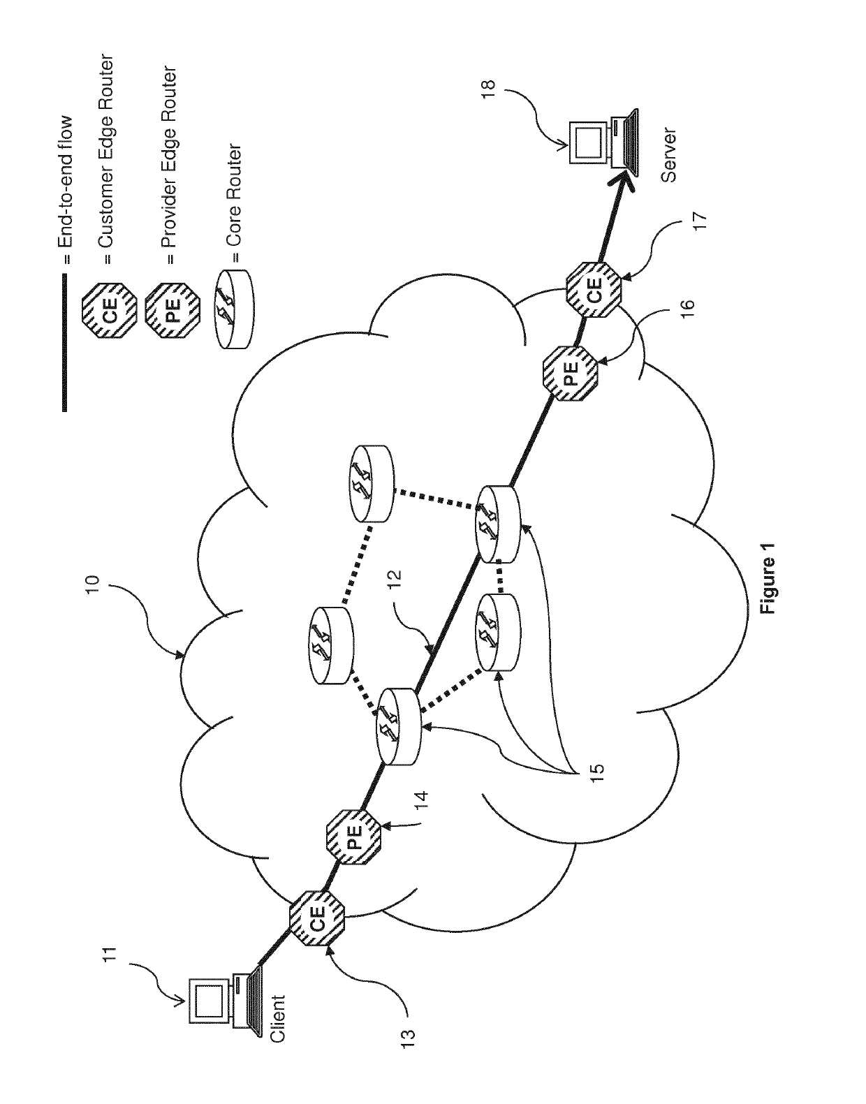
[0040]a communications network 10 of the present invention will now be described with reference to FIGS. 1 to 2b. The communications network 10 is a data packet network having a client 11, a server 18, a plurality of customer edge routers 13, 17, a plurality of provider edge routers 13, 16, and a plurality of core routers 15. The client 11 sends data packets to the server 18 via path 12, which traverses a plurality of customer edge, provider edge and core routers. The skilled person will understand that other clients and servers may be connected to the customer edge routers, and other customer edge routers may be connected to the provider edge routers.

[0041]When the client 11 sends a data packet along path 12, it is initially forwarded to a first customer edge router 13, which forwards it on to the first provider edge router 14. The first provider edge router 14 forwards the data packet to a core router 15, which in turn forwards it on to a second provider edge router 16 (which may ...

second embodiment

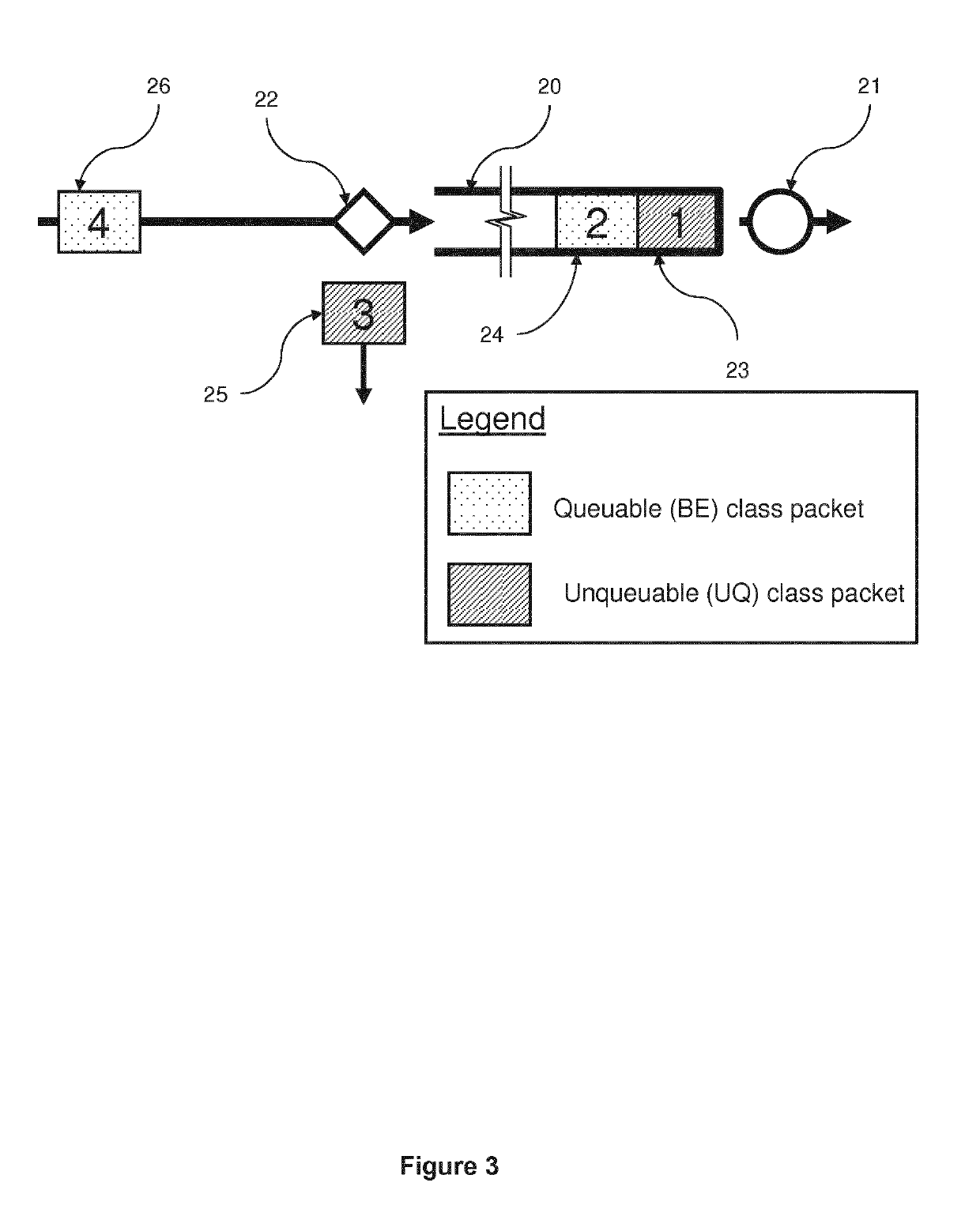
[0051]A flow diagram illustrating the management function 22 of the processor 15b is shown in FIG. 5b. In this embodiment, the steps of determining whether the buffer is empty and determining whether the packet is unqueuable are reversed.

[0052]The unqueuable class of service can be exploited by a sender / receiver node 11, 18 pair in order to determine an appropriate transfer rate to use in the communications network 10 (i.e. the maximum rate at which data can be transmitted without causing any packets to be dropped or causing packets on data flow sharing part of the same transmission path to be dropped). Before an embodiment of this algorithm is described, an overview of the conventional TCP Slow-Start process and its corresponding timing diagram will be presented with reference to FIG. 6.

[0053]FIG. 6 is a timing diagram in which two time axes extend downwardly from a client (e.g. client 11) and a server (e.g. server 18). Various data packets are represented by arrows extending betwe...


PUM


Abstract

The invention includes a network node, and a method of controlling the network node in a data packet network, wherein the method comprising the steps of: receiving a first data packet from a first external network node; analysing the first data packet to determine if it is of a class of service deemed to be queuable or unqueuable; and, if it is queuable, sending the first data packet to a second external node via an intermediate node, wherein the first data packet is reclassified to be of the unqueuable class of service such that the intermediate node should not forward the first data packet to the second external network node if a packet queue exists at the intermediate node.

Description

FIELD OF THE INVENTION[0001]The present invention relates to a data packet network and to a method of controlling packets in a data packet network.BACKGROUND[0002]A majority of networks in use today use discrete data packets which are transferred between a sender and receiver node via one or more intermediate nodes. A common problem in these data packet networks is that the sender node has little or no information on the available capacity in the data packet network, and thus cannot immediately determine the appropriate transmission rate at which it may send data packets. The appropriate transmission rate would be the maximum rate at which data packets can be sent without causing congestion in the network, which would otherwise cause some of the data packets to be dropped and can also cause data packets on other data flows (e.g. between other pairs of nodes which share one or more intermediate nodes along their respective transmission paths) to be dropped.[0003]To address this probl...

Claims


Application Information

Patent Timeline
Patent Type & Authority Applications(United States)
IPC IPC(8): H04L12/851H04L12/835H04L12/823H04L12/801H04L47/30H04L47/31H04L47/32
CPCH04L47/30H04L47/12H04L47/2441H04L47/32H04L47/2458H04L47/24H04L47/31
Inventor BRISCOE, ROBERTEARDLEY, PHILIP
Owner BRITISH TELECOMM PLC
Features
  • R&D
  • Intellectual Property
  • Life Sciences
  • Materials
  • Tech Scout
  • Unparalleled Data Quality
  • Higher Quality Content
  • 60% Fewer Hallucinations
Learn More