Die clearance monitoring system for a crimping device

a technology of clearance monitoring and crimping device, which is applied in the manufacture of contact parts, presses, manufacturing tools, etc., can solve the problems of manual inspection relative inaccurate, have to be discarded, and crimp terminal assemblies that fail to meet specifications

Active Publication Date: 2020-01-30
TYCO ELECTRONICS LOGISTICS AG (CH)
View PDF0 Cites 3 Cited by
  • Summary
  • Abstract
  • Description
  • Claims
  • Application Information

AI Technical Summary

Benefits of technology

This patent describes a system for measuring the space between two crimp dies in a crimping device used to make electrical connections. A light source shines bright light onto the area where the crimp dies are located, and a camera detects how much of this light makes it back out after passing through the gaps between the crimp dies. By analyzing these measurements, the system can calculate the distance between the crimp dies during use. This helps ensure consistent quality when making electrical connections.

Problems solved by technology

The technical problem addressed in this patent text is the need for a system to automatically monitor the position of crimp dies on crimping devices to ensure consistent and accurate production of crimped terminal assemblies that meet specifications. Current methods of manual inspection are inefficient and unreliable, causing waste and downtime for the crimping device.

Method used


Image

  • Die clearance monitoring system for a crimping device
  • Die clearance monitoring system for a crimping device
  • Die clearance monitoring system for a crimping device

Examples


Embodiment Construction

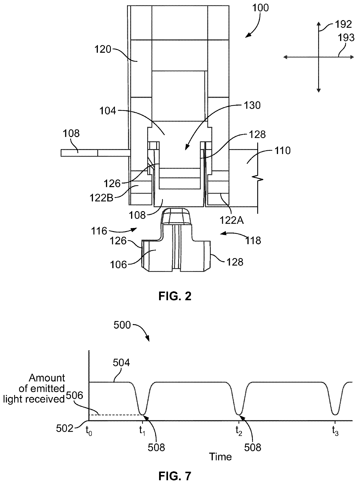
[0017]Embodiments of the present disclosure provide a die clearance monitoring system for a crimping device and a crimping device that incorporates the die clearance monitoring system. The die clearance monitoring system utilizes the transmission of light (e.g., electromagnetic radiation) to detect the clearance or spacing between mating crimp dies of a die set of the crimping device. For example, photons of light may be emitted from one side or end of the die set, and a detector on the opposite side or end of the die set measures an amount of the light that traverses across the die set between the mating crimp dies. Based on the amount of light received by the detector across the die set, the die clearance monitoring system determines the relative spacing (e.g., a size of a clearance gap) between the crimp dies.

[0018]At least one technical effect of the embodiments of the die clearance monitoring system disclosed herein is the ability to receive timely feedback even during operatio...


PUM

PropertyMeasurementUnit
Wavelengthaaaaaaaaaa
Lightaaaaaaaaaa

Abstract

A die clearance monitoring system includes a light source, a light detector, and a controller. The light source is disposed along a front side of a die set of a crimping device and emits light towards the die set. The die set includes a first crimp die and a second crimp die that engage and crimp an object along a crimp stroke. The light detector is disposed along a rear side of the die set. The light detector receives the emitted light from the light source that traverses across the die set through a gap defined between the first and second crimp dies and generates light absorption data based on the emitted light that is received. The controller is communicatively connected to the light detector. The controller processes the light absorption data to determine a relative spacing between the first crimp die and the second crimp die.

Description


Claims


Application Information

Patent Timeline
Owner TYCO ELECTRONICS LOGISTICS AG (CH)
Why Eureka
Try Eureka