
Draw latch

a technology of latches and latches, applied in the field of draw latches, can solve the problems of rubber prone to perishing in time, metal parts tend to wear, worn metal latches do not work properly,

Inactive Publication Date: 2020-03-19
TIETOSET
View PDF0 Cites 1 Cited by
  • Summary
  • Abstract
  • Description
  • Claims
  • Application Information

AI Technical Summary

Benefits of technology

The present invention provides a durable and safe draw latch for latching together two closure members of a watercraft. The latch includes a keeper, base, lever, locking member, and metal housing. The locking member is connected to the lever by a pin and can pivot around the pin's axis. There is a gap between the locking member and the metal housing. The connection between the lever and the base is closer to the second closure member than to the keeper when the latch is in the latched position. The metal housing has at least one locking hole and the base has at least one opening that align when the latch is in the latched position, allowing for locking using padlock. The elastic material used is rubber or steel. The keeper is a flat sheet with a middle portion that folds to detent the latch when it is in the latched position. The locking member has a transverse shaft or a pin that runs through the metal housing and the locking member to secure the latch. This invention solves the problem of previous draw latches being less durable and safe.

Problems solved by technology

However, in use metal parts tends to wear and they may loosen in time.
Thus, worn metal latches do not work properly and may even open by themselves.
However, the rubber tends to perish in time, especially when it is exposed to environmental conditions such as ultraviolet radiation and weather.
Rubber draw latches are also easy to cut open and, thus, they are weak against burglary.

Method used


Image

  • Draw latch
  • Draw latch
  • Draw latch

Examples


Embodiment Construction

[0030]The draw latches are used for latching two closure members. The closure members are not shown in the figures as they are not part of the invention as such. However, the closure members are used in the description for understanding the invention better.

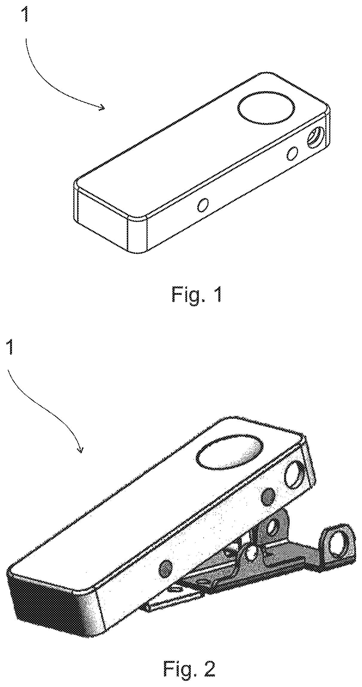
[0031]FIG. 1 shows a draw latch 1 in a latched position and FIG. 2 shows a draw latch 1 in an open position. As seen, the housing of the draw latch is the only visible part and no internal parts are shown when the draw latch is in latched position. As the internal parts are covered by the housing, they are not exposed to the external conditions such as rain, ultraviolet radiation (UV-radiation), and external forces such as impacts. When the draw latch is in the open position, some of the internal parts are exposed as seen in FIG. 2.

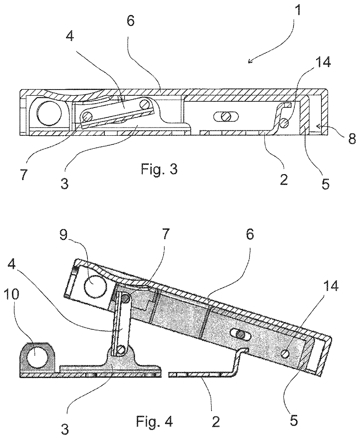
[0032]FIG. 3 shows a cross section of the draw latch in the latched position and FIG. 4 shows a cross section of the draw latch in the open position. The draw latch comprises a keeper 2, a base 3, a le...


PUM


Abstract

A draw latch (1) for latching together two closure members of a watercraft, which draw latch have an open position, wherein the two closure members are not latched, and a latched position, wherein the two closure members are secured, comprising a keeper (2) arranged to be attached to a first closure member, a base (3) arranged to be attached to a second closure member, a lever (4) pivotally connected to the base (3), a locking member (5), made of elastic material, pivotally connected to the lever (4), and arranged to be affixed to the keeper (2) when the draw latch is in the latched position. The draw latch further comprises a metal housing (6) arranged to cover the keeper, base, lever and elastic locking member against the two closure members when the keeper is attached to the first closure member, the base is attached to the second closure member and the draw latch is in the latched position.

Description

TECHNICAL FIELD[0001]The present invention relates to a device for securing two closure members together.BACKGROUND OF THE ART[0002]Known draw latches comprise generally a keeper and a one-piece part having three segments such as a base segment, a locking segment and an intermediate segment wherein the intermediate segment is connected to the base and locking segments. When in a latched condition, the locking segment is detachably connected to the keeper and is in overlaying relation to the keeper, the base segment and the intermediate segment. Typically latches are made of metal to achieve a needed durability against environmental conditions and protection against external forces. However, in use metal parts tends to wear and they may loosen in time. Thus, worn metal latches do not work properly and may even open by themselves.[0003]In some applications, it is known to use rubber locking segments which, in a latched condition, are stretched over the keeper. However, the rubber tend...

Claims


Application Information

Patent Timeline
IPC IPC(8): E05C19/14E05B67/38E05B13/10B63B19/00
CPCE05B67/383E05C19/14B63B2019/0069B63B19/00E05B13/10E05Y2900/514E05B13/002E05B17/002E05B67/02E05B2015/165
Inventor SIISKONEN, ANTTI
Owner TIETOSET
Learn More