Pitot tube heater assembly

a heater and pipe tube technology, applied in the field of aircraft sensors, can solve the problems of ice accumulation on the pipe tube and failure of the heater assembly,

Active Publication Date: 2020-04-09
ROSEMOUNT AEROSPACE
View PDF0 Cites 9 Cited by
  • Summary
  • Abstract
  • Description
  • Claims
  • Application Information

AI Technical Summary

Benefits of technology

[0016]Additionally or alternatively, in this or other embodiments a layer of braze paste is applied to the tube sleeve prior to securing the tube sleeve into the outer tube, and the tube sleeve is secured to the outer tube via brazing.
[0017]Additionally or alternatively, in this or other embodiments one or more drain openings are formed in the pitot tube, extending from the tube passage through the tube sleeve and through the outer tube for egress of fluid from the tube passage.

Problems solved by technology

In certain flight conditions, the pitot tube may be subject to ice accumulation from moisture in the air.
Further, in other conditions, the pitot tube may ingest ice crystals which then accumulate inside of the pitot tube and cause failure in its operation.

Method used


Image

  • Pitot tube heater assembly
  • Pitot tube heater assembly
  • Pitot tube heater assembly

Examples


Embodiment Construction

[0034]A detailed description of one or more embodiments of the disclosed apparatus and method are presented herein by way of exemplification and not limitation with reference to the Figures.

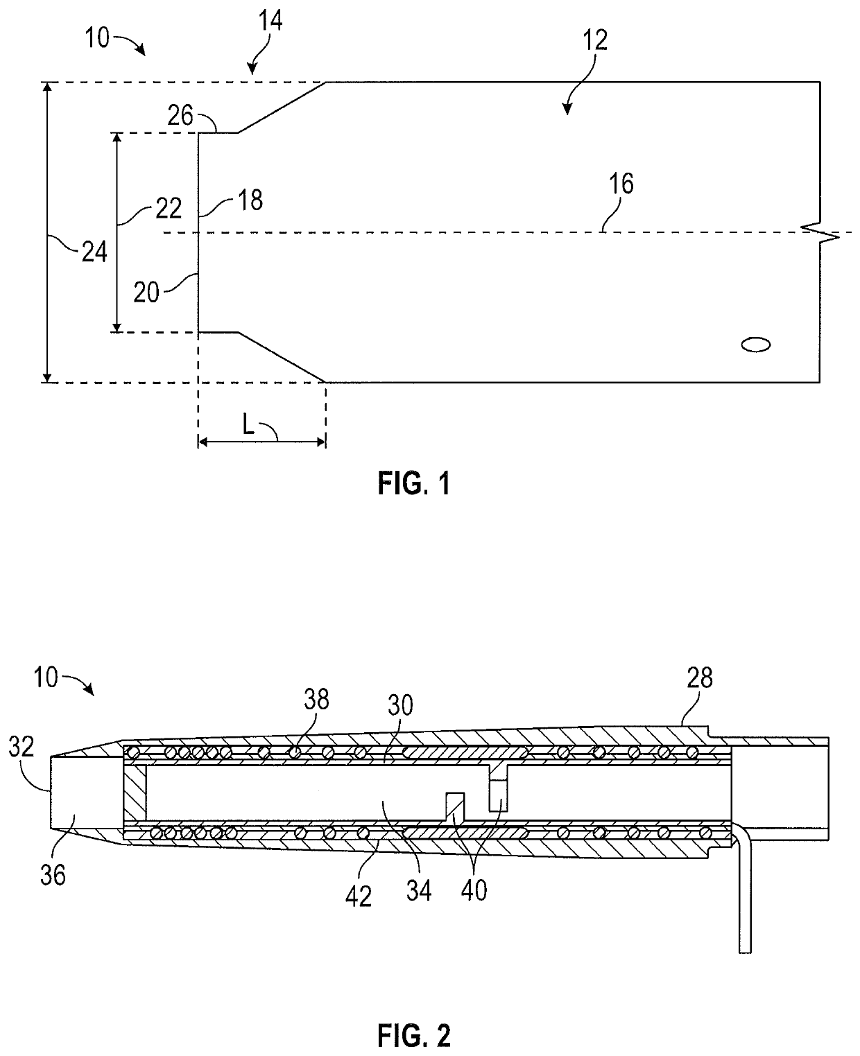
[0035]Referring to FIG. 1, illustrated is an embodiment of a sensor, in this embodiment a pitot tube 10. The pitot tube 10 includes a cylindrical body portion 12 and a tip portion 14 extending along a tube axis 16 from the body portion 12 toward a tube inlet 18. In the embodiment of FIG. 1, the tip portion 14 includes an inlet opening 20 having an inlet diameter 22 smaller than a body diameter 24 of the body portion 12. The tip portion 14, between the body portion 12 and the inlet opening 20, tapers in diameter along a concave curve 26. In some embodiments, the concave curve 26 does not extend entirely to the inlet opening 20 as the inlet diameter 22 extends axially from the inlet opening 20 to the concave curve 26. It shall be understood that the curve 26 may be straight or a profile that is aer...


PUM

PropertyMeasurementUnit
shapeaaaaaaaaaa
velocitiesaaaaaaaaaa
stagnation pressureaaaaaaaaaa

Abstract

A pitot tube includes an outer tube extending from a first tube end to second tube end. The second tube end defines a tip portion of the pitot tube. A tube sleeve is located inside of the outer tube and defines a tube passage extending from the first tube end to the second tube end. A heating element is located between the outer tube and the tube sleeve. The heating element is isolated from airflow into the tube passage. A method of forming a pitot tube includes installing a heating element to an outer surface of a tube sleeve, the tube sleeve defining a tube passage of the pitot tube. The tube sleeve is secured in an outer tube such that the heating element is between the tube sleeve and the outer tube and is isolated from airflow through the tube passage.

Description

FOREIGN PRIORITY[0001]This application claims priority to India Patent Application No. 201811037757, filed Oct. 5, 2018, and all the benefits accruing therefrom under 35 U.S.C. § 119, the contents of which in its entirety are herein incorporated by reference.BACKGROUND[0002]Exemplary embodiments pertain to the art of aircraft sensors such as pitot tubes, and more particularly to ice prevention and removal from such sensors.[0003]A pitot tube is widely used to determine airspeed of an aircraft or other vehicle, or to measure air or gas velocities in industrial applications. In particular, by measuring stagnation pressure of a fluid driven into the pitot tube, together with a measured static pressure, the airspeed of the aircraft can be determined. In certain flight conditions, the pitot tube may be subject to ice accumulation from moisture in the air. For this reason, pitot tubes are equipped with heating elements to prevent such ice accumulation. Further, in other conditions, the pi...

Claims


Application Information

Patent Timeline
Patent Type & Authority Applications(United States)
IPC IPC(8): G01F15/10F16L33/22G01P5/165G01L19/04
CPCG01L19/04F16L33/223G01P5/165G01F15/10H01C17/04
Inventor JACOB, ROBINMAHAPATRA, GURU PRASADJOHNSON, PAUL ROBERT
Owner ROSEMOUNT AEROSPACE
Why Eureka
Try Eureka