Orthodontic system and method of use

Pending Publication Date: 2020-09-24
ARIZA JOAQUIN T
View PDF0 Cites 1 Cited by
  • Summary
  • Abstract
  • Description
  • Claims
  • Application Information

AI Technical Summary

Benefits of technology

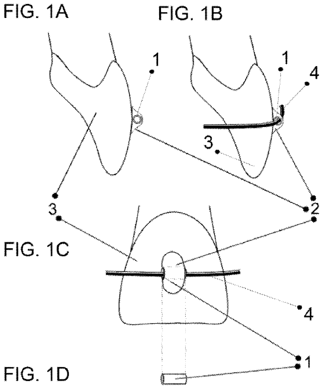
[0013]In another example, a method for performing an orthodontic treatment is presented. The method may include providing an arch wire that includes one or more pins extending outwardly and configured to register vertically with a tube, the tube including at least one sidewall and two opening ends that form a tubular passage adapted to receive a portion of one of the one or more pins; adhering the tube with a luting agent to a tooth on a labial side or a lingual side of a dental arch of a patient, the tube positioned vertically on a surface of the tooth; positioning the arch wire to align a pin of the one or more pins of the arch wire with the tube; and inserting the pin into the at tube.
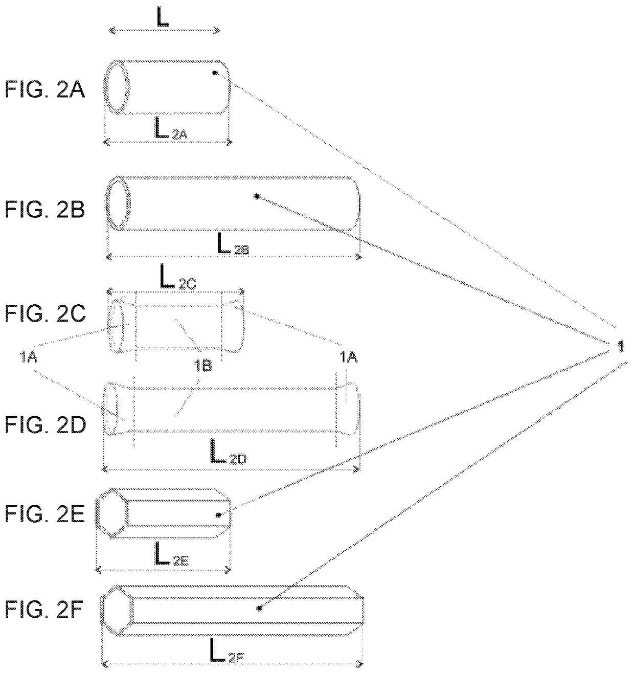
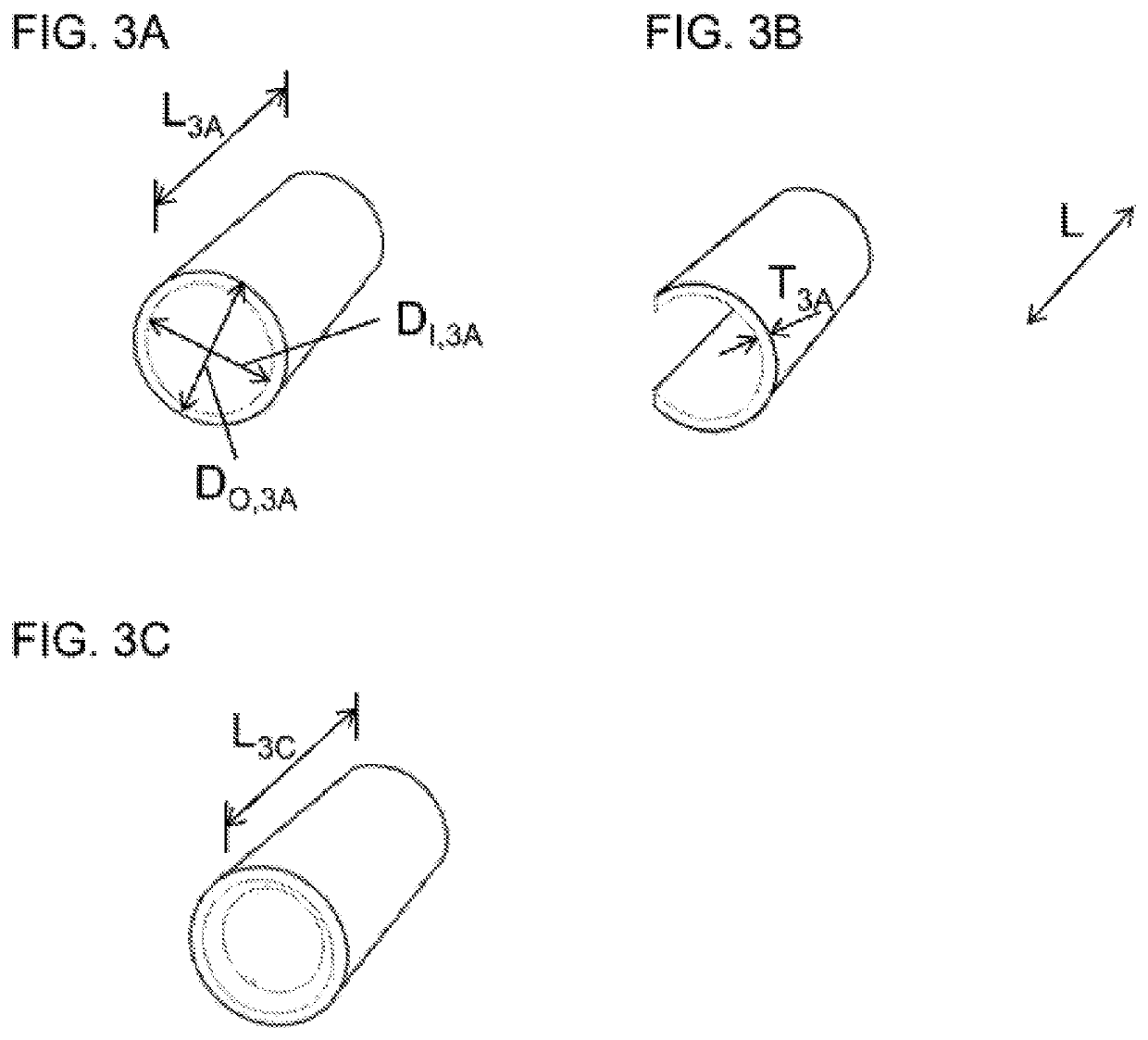
[0014]In yet another example, an orthodontic system is presented. The orthodontic system includes a tube having at least one sidewall and two opening ends, and a luting agent. The luting agent is disposed on at least a portion of one or more of the at least one sidewall of the tube and a portion of a surface of a tooth onto which the tube is directly attached or adhered. The two opening ends of the tube remain substantially open so that a wire can move along the tube.
[0015]In yet another example, an orthodontic system is presented. The orthodontic system includes a tube having at least one sidewall and two opening ends. One or more of the at least one sidewall having a pre-applied luting agent. One of the one or more sidewalls can be pressed against a surface of a tooth so that the pre-applied luting agent attaches the tube directly onto the surface of the tooth. The two opening ends of the tube remain substantially open so that a wire can move along the tube.
[0016]In a different example

Problems solved by technology

Historically, the process of orthodontics to place brackets involves a number of steps and procedures that not only increase the time to attend a patient in a clinical appointment and the likelihood of errors in each step performed by the orthodontist but also may increase the discomfort of the patient.
This is at least partially due to the complex shape and the big size of the conventional appliances (brackets), which makes difficult to try to

Method used


Image

  • Orthodontic system and method of use
  • Orthodontic system and method of use
  • Orthodontic system and method of use

Examples


Embodiment Construction

[0050]In the following discussion that addresses a number of embodiments and applications of the present invention, reference is made to the accompanying drawings that form a part thereof, where depictions are made, by way of illustration, of specific embodiments in which the invention may be practiced. It is to be understood that other embodiments may be utilized and changes may be made without departing from the scope of the invention. Wherever possible, the same reference numbers are used in the drawings and the following description to refer to the same or similar elements.

[0051]In the following detailed description, numerous specific details are set forth by way of examples in order to provide a thorough understanding of the relevant teachings. However, it should be apparent to those skilled in the art that the present teachings may be practiced without such details. In other instances, well known structures, components and / or functional or structural relationship thereof, etc....


PUM


Abstract

The present disclosure relates to an orthodontic system and a method of using the same to perform orthodontics. In one example, an orthodontic system is presented. The orthodontic system includes a tube having at least one sidewall and two opening ends, and a luting agent. The luting agent is disposed on at least a portion of one or more of the at least one sidewall of the tube and a portion of a surface of a tooth onto which the tube is directly attached or adhered. The two opening ends of the tube remain substantially open so that a wire can move along the tube.

Description

CROSS-REFERENCE TO RELATED APPLICATIONS[0001]The present application is a continuation-in-part application claiming the benefit of priority to U.S. patent application Ser. No. 15 / 912,535, filed Mar. 5, 2018, which in turn is a continuation-in-part application claiming the benefit of priority to U.S. patent application Ser. No. 14 / 581,021, filed Dec. 23, 2014, which in turn is a continuation-in-part claiming the benefit of priority to U.S. patent application Ser. No. 14 / 300,975, filed Jun. 10, 2014, which in turn is a divisional application claiming the benefit of priority to U.S. patent application Ser. No. 12 / 548,407, filed Aug. 26, 2009, each of which is hereby incorporated by reference.TECHNICAL FIELD OF THE INVENTION[0002]The present disclosure relates to dentistry. Specifically, the present disclosure relates to an orthodontic system and a method of using the same to perform orthodontic care.COPYRIGHT AND TRADEMARK NOTICE[0003]A portion of the disclosure of this patent applicat...

Claims


Application Information

Patent Timeline
IPC IPC(8): A61C7/28
CPCA61C7/282A61C7/12A61C7/141A61C7/04
Inventor ARIZA, JOAQUIN T.
Owner ARIZA JOAQUIN T
Why Eureka
Try Eureka