System for producing a dental implant and method

a technology for dental implants and dental crowns, applied in the field of dental implants, can solve the problems of difficult bone integration, difficult implant placement, and frequent problems such as the appearance of such blade implants

Inactive Publication Date: 2005-06-30
D4D TECH LP
View PDF17 Cites 109 Cited by
  • Summary
  • Abstract
  • Description
  • Claims
  • Application Information

AI Technical Summary

Problems solved by technology

At times, problems occur with such blade implants due to epithelium growing between the blade and the bone as a result of micromotion or overheating of the bone during preparation, incorrect texture of the surface, or placement of the blade in less dense cancellous bone.
This often provides a challenge of using an implant of the correct size in length and diameter in order to provide the strength to bear the load.
When a fresh extraction has taken place, the placement of an implant often poses a challenge.
This is due to the socket or void in the bone being much longer than most implants and even when larger or expandable implants are employed, they periodically have difficulty properly integrating with the bone.
Additionally, conventional implantation involving fresh extraction often requires preparation that is apical to the extraction site which tends to be a more invasive procedure.
This invasive approach requires a high degree of training, involves high cost and requires a lengthy healing time.

Method used


Image

  • System for producing a dental implant and method
  • System for producing a dental implant and method
  • System for producing a dental implant and method

Examples


Embodiment Construction

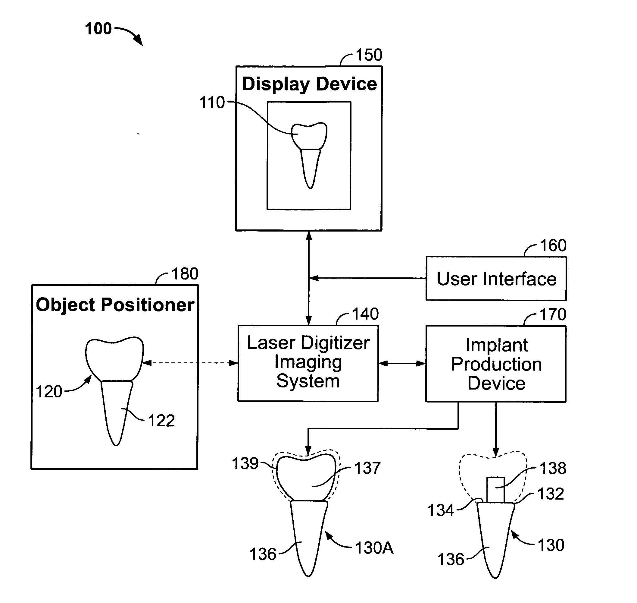
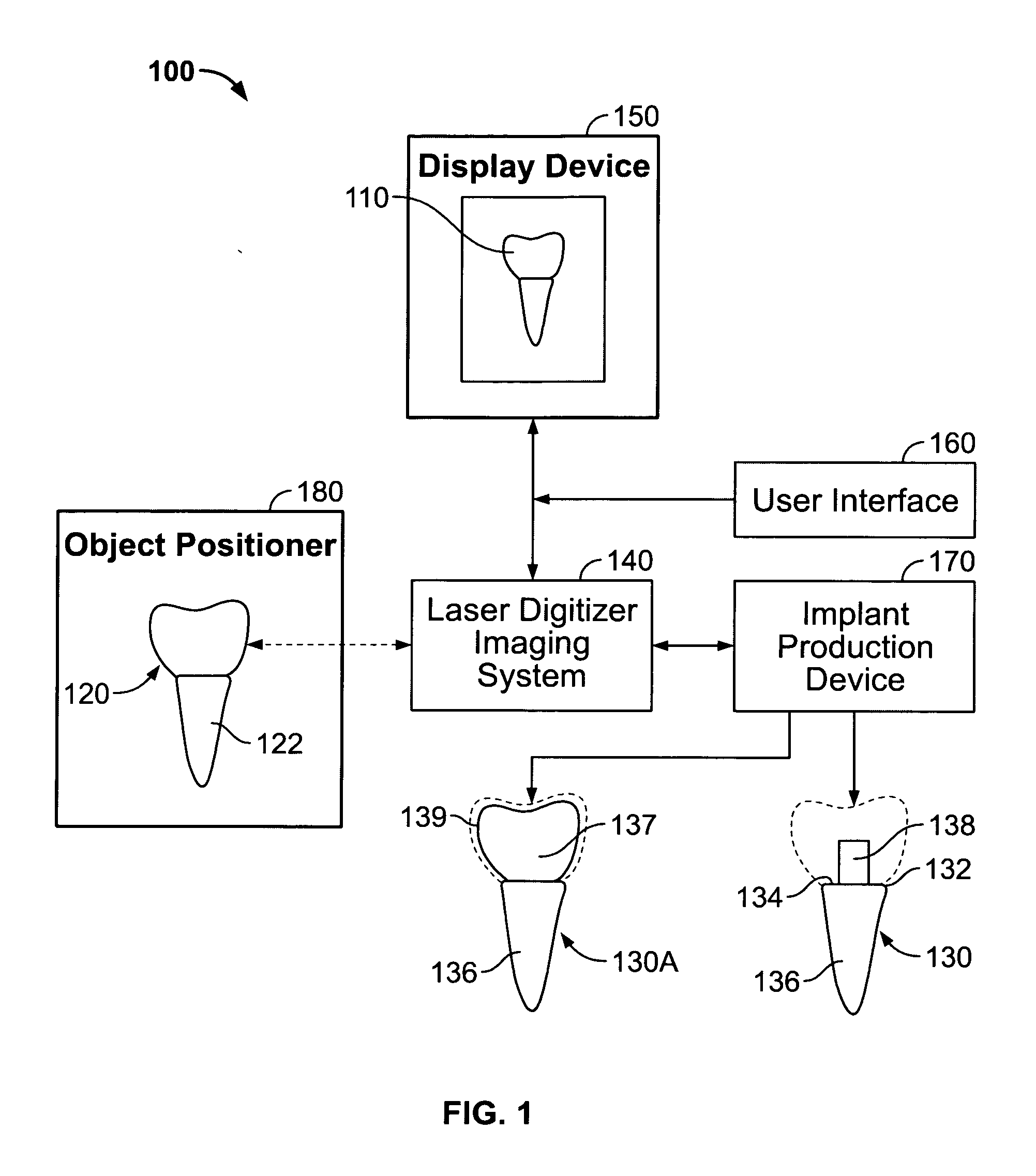
[0028]FIG. 1 illustrates an example of a dental implant production system 100 configured to generate a three-dimensional image 110 of a dental item such as a tooth 120 and for producing a dental implant 130 from the image obtained from the tooth. The dental item may alternatively be a dental impression formed from inserting impression material into a socket at an extraction site from where a tooth was removed. The dental impression formed is imaged and a dental implant is produced from data associated with the image of the dental impression. Other dental items may include bridges, inlays, crowns, onlays, copings, frameworks, veneers and the like. The dental implant production system 100 includes an imaging system 140, display device 150, user interface 160, and implant production device 170. The dental implant production system 110 may also include an object positioner 180 to hold and position an extracted tooth or other dental item 120 within a field of projection of the imaging sy...


PUM


Abstract

A system and method for producing a dental fixture are provided. A laser digitizer imaging system creates a visual three-dimensional image of a dental item such as a tooth or a dental impression. The three-dimensional image may be displayed and the size and shape of the image may be selectively modified by the user of the system. Digital data associated with the three-dimensional image of the dental item is sent to an implant production device. A dental implant is produced in response to receipt of the data associated with the three-dimensional image such that the implant is insertable into a socket of the jawbone from where a tooth was extracted.

Description

CROSS REFERENCE TO RELATED APPLICATIONS [0001] This application is a continuation-in-part of U.S. patent application Ser. No. 10 / 749,579 filed Dec. 30, 2003 entitled “Laser Digitizer System for Dental Applications”, and a continuation-in-part of U.S. patent application Ser. No. 10 / 804,694 filed Mar. 19, 2004 entitled “Laser Digitizer System for Dental Applications”, and a continuation-in-part of U.S. patent application Ser. No. 10 / 840,480 filed May 5, 2004 entitled “Optical Coherence Tomography Imaging”, and a continuation-in-part of U.S. patent application Ser. No. 10 / 917,069 filed Aug. 12, 2004 entitled “Improved Milling Machine”, the complete disclosures of which are incorporated by reference herein.BACKGROUND OF THE INVENTION [0002] 1. Related Field [0003] The invention relates to dental implants and systems and methods for producing and preparing dental implants. [0004] 2. Description of the Related Art [0005] A dental implant may be inserted into the jawbone of a patient to pr...

Claims


Application Information

Patent Timeline
Patent Type & Authority Applications(United States)
IPC IPC(8): A61C8/00A61C9/00A61C13/00
CPCA61C13/0004A61C9/004A61C9/0053A61C5/77
Inventor FRYSH, HOWARDQUADLING, HENLEY S.QUADLING, MARK S.
Owner D4D TECH LP
Why Eureka
Try Eureka