Supercharge Your Innovation With Domain-Expert AI Agents!

Protocols and Architectures for NR-NR Dual Connectivity (NR-DC)

a technology of dual connectivity and protocols, applied in the field of wireless communication networks, can solve the problems of blockage of more urgent and smaller srb1 messages, various difficulties, issues and/or ambiguities in the operation of ues and/or networks, and achieve the effect of facilitating earlier market introduction of such features, reducing implementation and testing efforts, and facilitating unified and consistent ue behavior

Active Publication Date: 2021-02-04
TELEFON AB LM ERICSSON (PUBL)
View PDF0 Cites 1 Cited by
  • Summary
  • Abstract
  • Description
  • Claims
  • Application Information

AI Technical Summary

Benefits of technology

This approach reduces implementation and testing efforts, enabling earlier market introduction of dual-RRC features, improving throughput and reducing delays in wireless communication networks.

Problems solved by technology

SRB2 has a lower priority than SRB1, because logged measurement information and NAS messages can be lengthy and could cause the blocking of more urgent and smaller SRB1 messages.
Moreover, the combination of NR-DC with new NR base station (referred to as “gNB”) split architecture is expected to create various difficulties, issues and / or ambiguities in the operation of UEs and / or networks.

Method used


Image

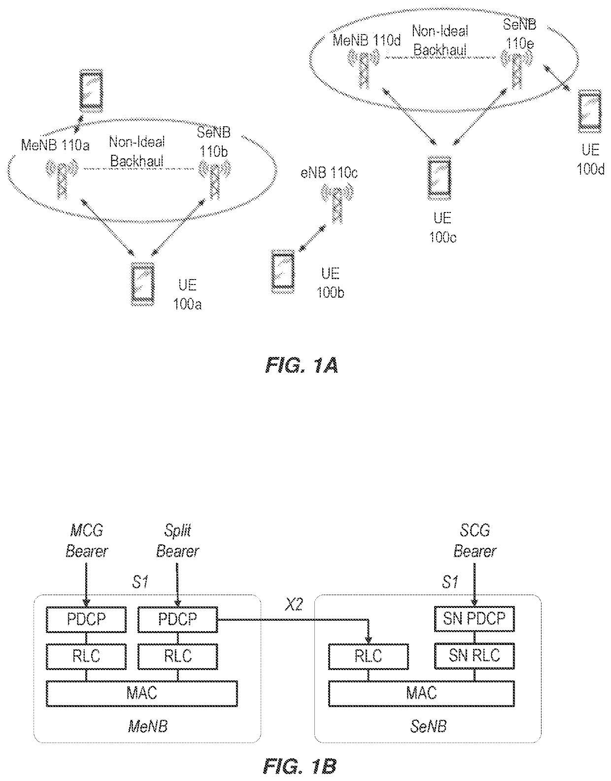
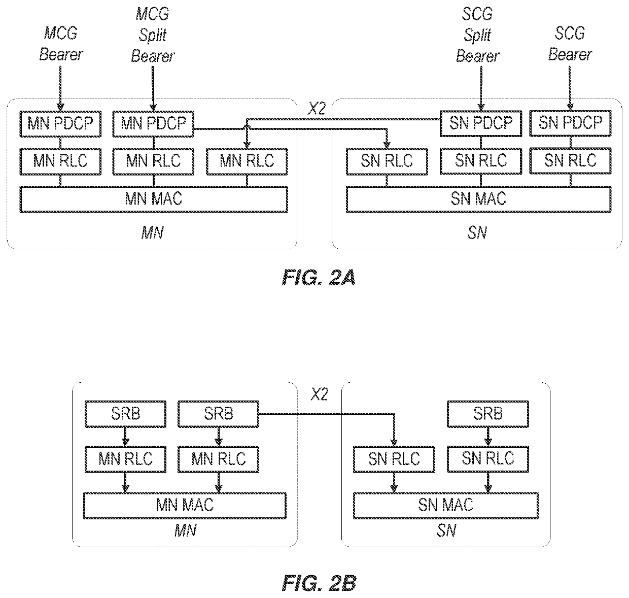
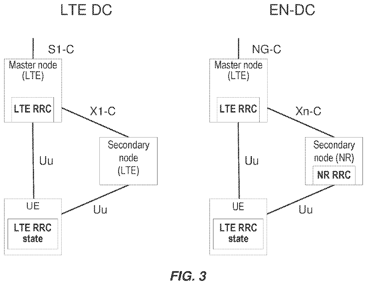
  • Protocols and Architectures for NR-NR Dual Connectivity (NR-DC)
  • Protocols and Architectures for NR-NR Dual Connectivity (NR-DC)
  • Protocols and Architectures for NR-NR Dual Connectivity (NR-DC)

Examples


embodiment 4

5. The method of embodiment 4, further comprising, if the second DU is associated with the CU, establishing the second SRB in association with the second RRC entity.

6. The method of embodiment 4, further comprising sending, to the UE via the first DU, an RRC message associated with the first RRC entity that comprises an encapsulated RRC message associated with the second RRC entity.

7. The method of embodiment 2, further comprising, if the second DU is associated with the CU:[0169]establishing the split bearer for the first SRB; and[0170]refraining from establishing the split bearer for the existing DRB established through the first DU.

8. The method of any of embodiments 1-2, wherein:[0171]the one or more further radio bearers comprises:[0172]a first further radio bearer comprising one of: the second SRB, and the split bearer for the first SRB; and[0173]a second further radio bearer comprising one of: the split bearer for the existing DRB, and one or more further DRBs; and[0174]deter...

embodiment 14

15. The method of embodiment 14, wherein establishing the one or more further radio bearers comprises establishing the second SRB, and further comprising initiating a second RRC entity within the UE to communicate with the second RRC entity within the CU via the second SRB.

16. The method of any of embodiments 13-15, further comprising, establishing the one or more further radio bearers in association with a security key that is also associated with the first radio bearer.

17. A wireless device configurable to communicate via a plurality of distributed units (DUs) in a radio access network (RAN), the wireless device comprising:[0189]processing circuitry configured to perform any of the steps of any of embodiments 13-16; and[0190]power supply circuitry configured to supply power to the wireless device.

18. A centralized unit (CU) in a radio access network (RAN) arranged to configure a user equipment (UE) to communicate via a plurality of distributed units (DUs), the CU comprising:[0191]...


PUM


Abstract

Embodiments include methods, for a first centralized unit (CU) in a radio access network (RAN), to configure a user equipment (UE) to communicate via first and second distributed units (DUs). Such methods include initiating a first radio resource control (RRC) entity to communicate with the UE via a first RRC connection through the first DU, and selecting the second DU to communicate with the UE in a dual-connectivity (DC) configuration with the first DU. Such methods include performing one or more of the following based on determining the second DU is associated with the first CU: initiating a second RRC entity within the first CU to communicate with the UE via a second RRC connection through the second DU; and establishing one or more further radio bearers with the UE via the second DU. Other embodiments include methods for a UE, and CUs and UEs configured to perform such methods.

Description

CROSS-REFERENCE TO RELATED APPLICATION(S)[0001]This application is a continuation of, and claims the benefit of priority from, U.S. application Ser. No. 16 / 464,330 filed on May 28, 2019, which is a national-stage application claiming priority to international application PCT / SE2019 / 050338 filed on Apr. 12, 2019, which claims the benefit of U.S. Appl. 62 / 669,436 filed on May 10, 2018. The entire disclosures of the above-mentioned applications are incorporated herein by reference for all purposes.TECHNICAL FIELD[0002]Embodiments of the present disclosure generally relate to wireless communication networks, and more specifically to establishing connections between a single user equipment (UE) and multiple base stations in a wireless communication network.INTRODUCTION[0003]Generally, all terms used herein are to be interpreted according to their ordinary meaning in the relevant technical field, unless a different meaning is clearly given and / or is implied from the context in which it is...

Claims


Application Information

Patent Timeline
Patent Type & Authority Applications(United States)
IPC IPC(8): H04W76/15
CPCH04W76/15H04W84/045H04W88/085H04W36/00692
Inventor TEYEB, OUMERFIORANI, MATTEOMILDH, GUNNAR
Owner TELEFON AB LM ERICSSON (PUBL)
Features
  • R&D
  • Intellectual Property
  • Life Sciences
  • Materials
  • Tech Scout
  • Unparalleled Data Quality
  • Higher Quality Content
  • 60% Fewer Hallucinations
Learn More