Determining air flow characteristic

a technology of air flow and characteristic, applied in the direction of indication/recording movement, engine control parameters, fluid speed measurement using thermal variables, etc., can solve the problems of insufficient reliability and robustness, complex post-processing, and difficult to determine local flow parameters at different radial positions

Inactive Publication Date: 2021-02-18
SIEMENS GAMESA RENEWABLE ENERGY AS
View PDF0 Cites 0 Cited by
  • Summary
  • Abstract
  • Description
  • Claims
  • Application Information

AI Technical Summary

Problems solved by technology

Local flow parameters at different radial positions, in contrast, are normally difficult to determine, as they most commonly require sensors in the flow outside of the blade.
In the context of field measurements of a wind turbine, there may be several drawbacks related to flow sensors such as those mentioned above as used in conventional methods.
Namely, these drawbacks may be related to for example interference of metallic elements with the lightning protection system of the turbine.
Further, they may require calibration of probes, may comprise uncertainty of the measurement signals, may require complex post-processing, may not provide sufficient reliability and robustness in harsh operational env

Method used


Image

  • Determining air flow characteristic
  • Determining air flow characteristic
  • Determining air flow characteristic

Examples


Embodiment Construction

[0055]The illustration in the drawings is in schematic form. It is noted that in different figures, similar or identical elements are provided with the same reference signs or with reference signs, which are different from the corresponding reference signs only within the first digit.

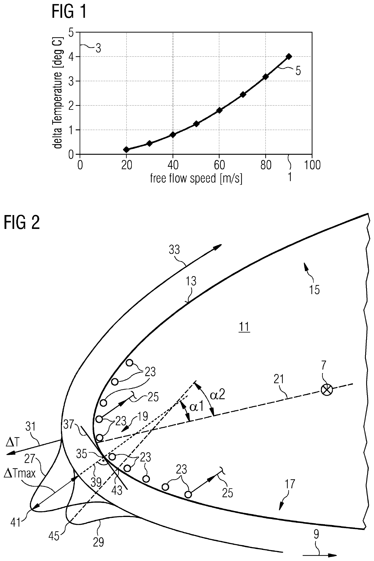
[0056]Embodiments of the present invention consider the temperature of air flow close to a surface of a rotor blade of a wind turbine. At a stagnation point where the air flow comes to a rest, the temperature increases depending on the Mach number of the fluid (i.e. the ratio of the speed of the fluid to the speed of the sound in the fluid) as well as on the so-called adiabatic constant of the fluid, normally referred to as gamma. If the fluid is air, the adiabatic constant is close to 1.4. The increase of temperature at the stagnation point relative to the static temperature of the fluid (i.e. the temperature in the free stream, in particular ambient temperature) may be expressed as:

T=T_inf * (1+M2* (g...


PUM


Abstract

It is described a method for determining a characteristic of air flow close to a surface of a rotating blade of a wind turbine, the method including: measuring at least one value of the temperature of air close to the surface of the blade; and deriving the characteristic of the air flow based on the temperature value.

Description

CROSS-REFERENCE TO RELATED APPLICATIONS[0001]This application claims priority to PCT Application No. PCT / EP2017 / 075536, having a filing date of Oct. 6, 2017, which is based off of EP Application No.17190855.1, having a filing date of Sep. 13, 2017, the entire contents both of which are hereby incorporated by reference.FIELD OF TECHNOLOGY[0002]The following relates to a method and arrangement for determining a characteristic of air flow close to a surface of a rotating blade of a wind turbine. Further, the following relates to a blade for a wind turbine and to a wind turbine comprising the blade and / or the arrangement. In particular, the following relates to a method and an arrangement for estimating the angle of attack of the flow at a given radial position of the blade, a method and an arrangement for estimating the flow speed at a given radial position and a method and an arrangement for determining the location of laminar to turbulent transition of the boundary layer at a given r...

Claims


Application Information

Patent Timeline
IPC IPC(8): F03D17/00
CPCF03D17/00F05B2270/325F05B2270/80F05B2270/321F05B2270/708F05B2270/32G01M9/065G01P5/10G01P13/006
Inventor EGEDAL, PERENEVOLDSEN, PEDER BAYFIEDEL, MORITZGONZALEZ, ALEJANDRO GOMEZ
Owner SIEMENS GAMESA RENEWABLE ENERGY AS
Why Eureka
Try Eureka