
Camera system, controller thereof, automobile, and deserializer circuit

a camera system and controller technology, applied in the field of data transmission technique, can solve the problems of increased area, increased cost of controller, and difference in updating timing between regions in a single image,

Active Publication Date: 2021-04-01
ROHM CO LTD
View PDF0 Cites 1 Cited by
  • Summary
  • Abstract
  • Description
  • Claims
  • Application Information

AI Technical Summary

Benefits of technology

The present patent is about a camera system that has multiple camera modules and a controller that manages them. The controller synchronizes the cameras and processes the video captured by them. The main technical effect is to adjust the frame synchronization signals for each camera module based on the time difference between the frame synchronization signal and the transmission synchronization signal, making the video images from each camera more accurate and reliable.

Problems solved by technology

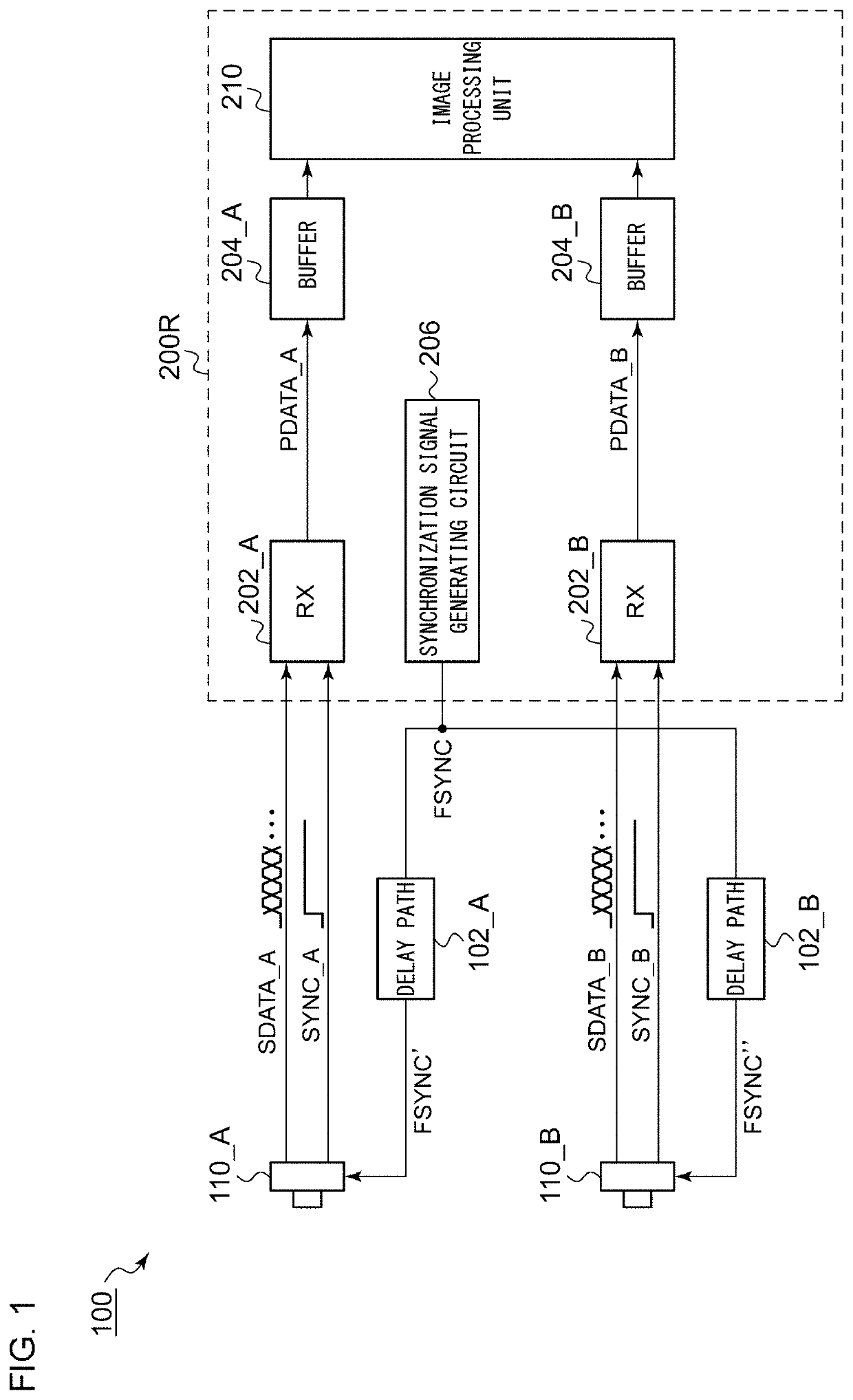
For example, in a case in which the image processing unit 210 integrates the frame data received from the camera module 110_A and the frame data received from the camera module 110_B so as to generate a signal image, such an arrangement has a problem in that there is a difference in updating timing between regions in a single image.
However, in a case in which each buffer 204 is configured to have an increased capacity, this leads to a problem of an increased area and an increased cost of the controller 200R.

Method used


Image

  • Camera system, controller thereof, automobile, and deserializer circuit
  • Camera system, controller thereof, automobile, and deserializer circuit
  • Camera system, controller thereof, automobile, and deserializer circuit

Examples


Embodiment Construction

1. Overview of the Embodiments

[0025]A summary of several example embodiments of the disclosure follows. This summary is provided for the convenience of the reader to provide a basic understanding of such embodiments and does not wholly define the breadth of the disclosure. This summary is not an extensive overview of all contemplated embodiments, and is intended to neither identify key or critical elements of all embodiments nor to delineate the scope of any or all aspects. Its sole purpose is to present some concepts of one or more embodiments in a simplified form as a prelude to the more detailed description that is presented later. For convenience, the term “one embodiment” may be used herein to refer to a single embodiment or multiple embodiments of the disclosure.

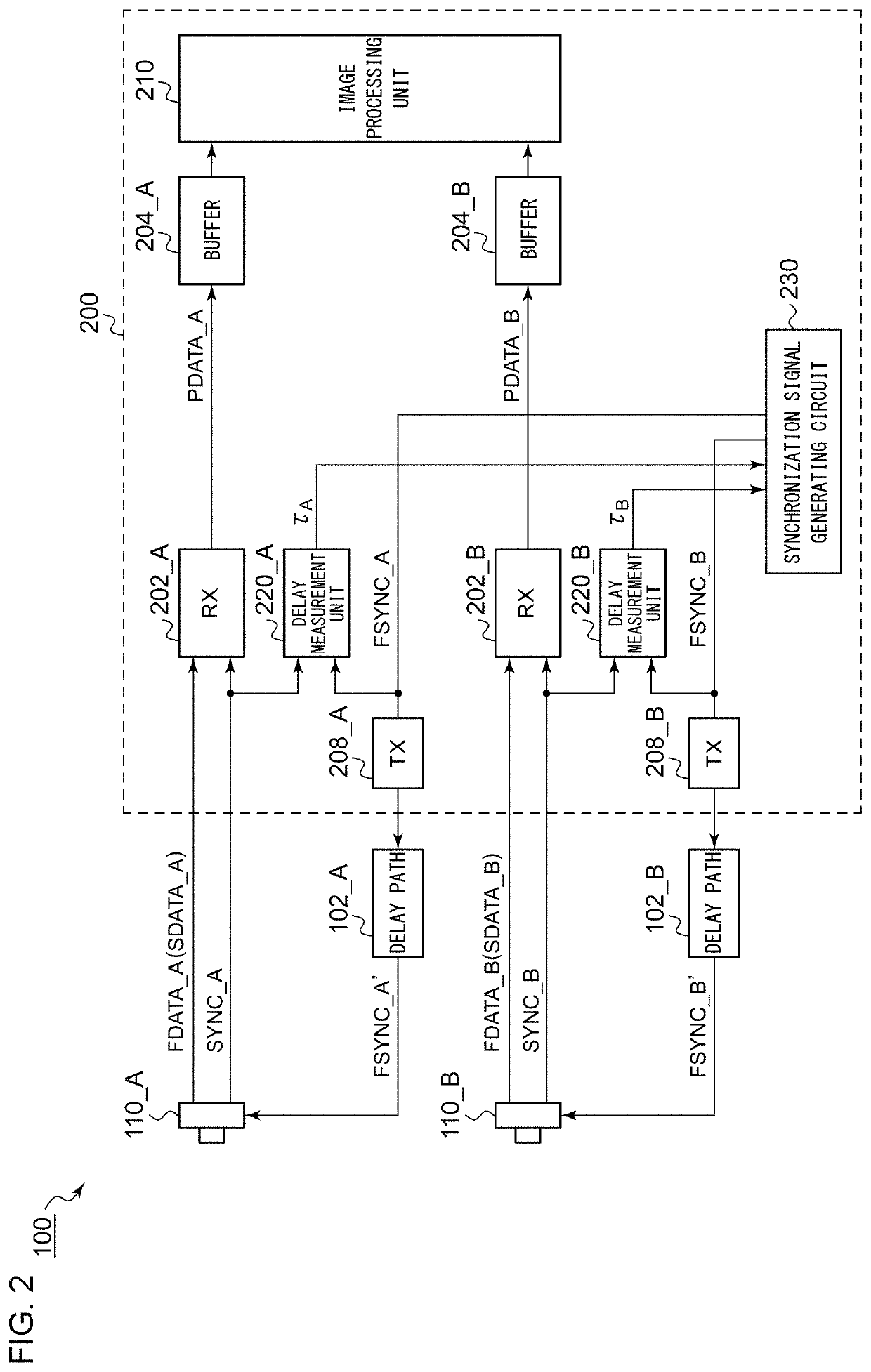
[0026]One embodiment relates to a camera system. The camera system includes: multiple camera modules; and a controller structured to control the multiple camera modules, and to process video images captured by the mult...


PUM


Abstract

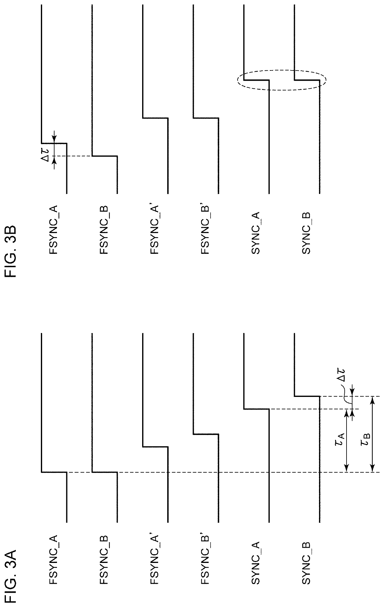
A controller controls multiple camera modules, and processes video images captured by the multiple camera modules. The controller is configured: (i) to output a frame synchronization signal FSYNC to each of the multiple camera modules; (ii) to receive frame data and a transmission synchronization signal SYNC that is synchronized with the frame data; (iii) to process the multiple items of frame data thus received; and (iv) to acquire a time difference between the corresponding frame synchronization signal and the corresponding transmission synchronization signal for each camera module, so as to adjust the timing of the frame synchronization signal according to the time difference.

Description

CROSS REFERENCE TO PRIOR APPLICATIONS[0001]This application is a continuation under 35 U.S.C. § 120 of PCT / JP2019 / 019321, filed May 15, 2019, which is incorporated herein reference and which claimed priority to Japanese Application No. 2018-111984, filed Jun. 12, 2018. The present application likewise claims priority under 35 U.S.C. § 119 to Japanese Application No. 2018-111984, filed Jun. 12, 2018, the entire content of which is also incorporated herein by reference.BACKGROUND1. Technical Field[0002]The present disclosure relates to a data transmission technique.2. Background Art[0003]A camera system configured to process video images captured by multiple cameras and to display a processed image is employed for an in-vehicle around view monitor or the like.[0004]FIG. 1 is a block diagram showing a camera system. A camera system 100R includes multiple camera modules 110 (two in this example), and a controller 200R. The controller 200R integrally controls the multiple camera modules ...

Claims


Application Information

Patent Timeline
Patent Type & Authority Applications(United States)
IPC IPC(8): H04N5/232H04N7/18H04N5/04
CPCH04N5/232H04N5/04H04N7/181H04N21/242H04N5/067H04N23/45H04N23/665H04N23/60
Inventor NAKAMURA, KENYA
Owner ROHM CO LTD
Learn More