Radio-Based Object Detection

Inactive Publication Date: 2021-04-22
SONY CORP
View PDF0 Cites 0 Cited by
  • Summary
  • Abstract
  • Description
  • Claims
  • Application Information

AI Technical Summary

Benefits of technology

[0014]Based on the request, at least one transmit angle of the radio waves may be determined. For example, based on the first location information or the scanning region provided in the request, a transmit angle of the radio waves may be determi

Problems solved by technology

However, in particular when monitoring objects near or on the ground, radar systems may suffer from disturbed radio w

Method used


Image

  • Radio-Based Object Detection
  • Radio-Based Object Detection
  • Radio-Based Object Detection

Examples


Embodiment Construction

[0029]In the following, exemplary embodiments of the present invention will be described in more detail. It is to be understood that the features of the various exemplary embodiments described herein may be combined with each other unless specifically noted otherwise. Same reference signs in the various drawings refer to similar or identical components. Any coupling between components or devices shown in the figures may be a direct or indirect coupling unless specifically noted otherwise.

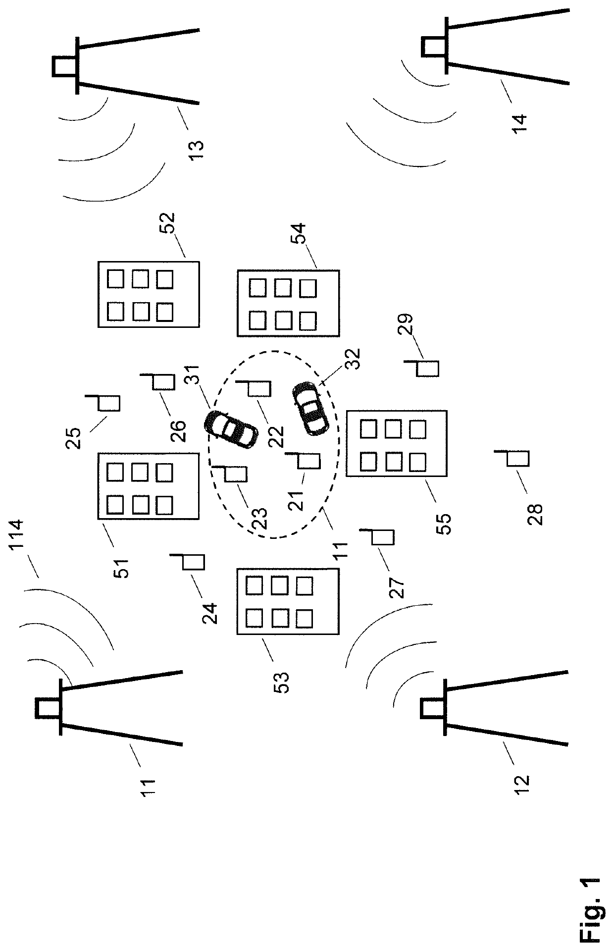
[0030]FIG. 1 shows schematically an arrangement of a plurality of first devices 11 to 14 and second devices 21 to 29.

[0031]The first devices 11 to 14 may comprise base stations of a wireless telecommunication network, for example a cellular wireless communication network. Additionally or as an alternative, the first devices 11 to 14 may comprise radar base stations equipped with modems for wireless communication, which may enable the radar base stations to communicate over cellular protocols.

[0032]T...


PUM


Abstract

The present invention relates to a radio-based object detection method. According to the method, first location information relating to an object of interest (31) are determined with a first device (11) using radio waves. Based on the first location information, a second device (21) from a plurality of candidate devices (21 to 29) is selected. A request for determining second location information relating to the object of interest (31) is transmitted via a telecommunication network to the second device (21).

Description

FIELD OF THE INVENTION[0001]The present invention relates to methods for detecting or locating objects in an environment using radio waves. The present invention relates furthermore to devices implementing the methods.BACKGROUND OF THE INVENTION[0002]Object detection, for example localizing and determining a movement of an object, may be advantageous or required in several applications, for example in vehicle control and monitoring systems of air-, land- or water-based vehicles, and monitoring of buildings and sites.[0003]For example, radar technology enables an accurate object detection. Radar is an object detection system that uses radio waves to determine the range, angle or velocity of objects. However, in particular when monitoring objects near or on the ground, radar systems may suffer from disturbed radio waves, for example absorbed, attenuated or reflected radio waves in urban environments, for example in street canyons.SUMMARY OF THE INVENTION[0004]In view of the above, the...

Claims


Application Information

Patent Timeline
IPC IPC(8): G01S13/87G01S13/42G01S7/00
CPCG01S13/872G01S7/003G01S13/42G01S13/87H04W40/20
Inventor LJUNG, RICKARDBENGTSSON, ERIKPERSSON, MAGNUSYING, ZHINONG
Owner SONY CORP
Why Eureka
Try Eureka