
Method for determining the risk of a user waking up in an undesirable state

a technology for determining a wake up indicator, which is applied in the field of measuring the risk of a user waking up in an undesirable state, can solve the problems of exacerbated sleep inertia, especially dangerous for shift workers, and impaired sleep inertia

Pending Publication Date: 2021-04-29
KONINKLJIJKE PHILIPS NV
View PDF4 Cites 1 Cited by
  • Summary
  • Abstract
  • Description
  • Claims
  • Application Information

AI Technical Summary

Benefits of technology

The patent describes a device that can be used to wake up people without making them uncomfortable or groggy. This device can detect when it is time to wake up and prevent the person from hitting the snooze button again. This technology uses a special indicator that helps people to wake up without losing any quality of sleep.

Problems solved by technology

Studies have even shown that the impairment caused by sleep inertia can be compared to the effects of alcoholic intoxication and may be especially dangerous for shift workers that need to make important decisions soon after awakening.
The presence of slow wave (deep) sleep prior to waking up tends to exacerbate sleep inertia with deeper sleep being more detrimental to the feeling of alertness in the morning.
During the transition from REM to wakefulness, the somatic motoneurons depolarize but that process is not necessarily immediate which can cause a feeling of muscle paralysis when waking up from REM sleep.
The severity of sleep inertia and sleep paralysis builds up with time.
Thus, a typical complaint from users using such alarms is that they are woken up too early and are deprived from the possibility to sleep longer.
These solutions also do not take into account the disadvantages associated with waking up from REM sleep and the fact that sleep inertia is analog i.e. a continuous process rather than binary (yes / no state).

Method used


Image

  • Method for determining the risk of a user waking up in an undesirable state
  • Method for determining the risk of a user waking up in an undesirable state
  • Method for determining the risk of a user waking up in an undesirable state

Examples


Embodiment Construction

[0052]The invention will be described with reference to the Figures.

[0053]It should be understood that the detailed description and specific examples, while indicating exemplary embodiments of the apparatus, systems and methods, are intended for purposes of illustration only and are not intended to limit the scope of the invention. These and other features, aspects, and advantages of the apparatus, systems and methods of the present invention will become better understood from the following description, appended claims, and accompanying drawings. It should be understood that the Figures are merely schematic and are not drawn to scale. It should also be understood that the same reference numerals are used throughout the Figures to indicate the same or similar parts.

[0054]The invention provides a method for measuring a wake up indicator, where the wake up indicator gives the likelihood of a user waking up undesirably. It is based on the knowledge that waking up during deep NREM sleep ...


PUM


Abstract

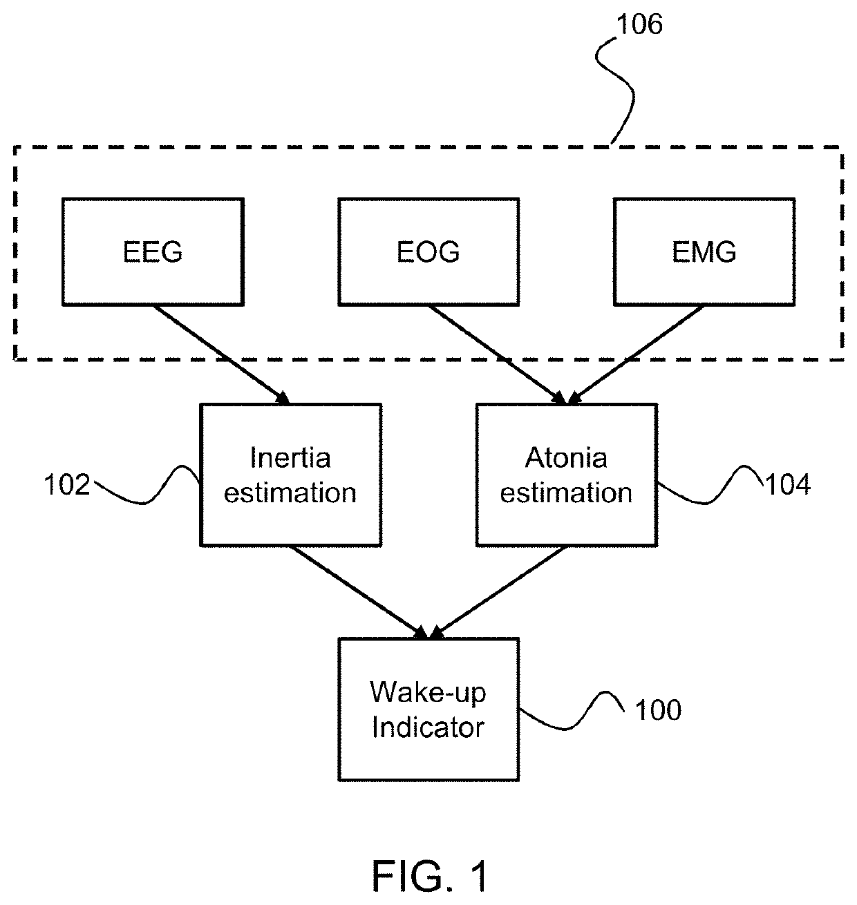
A method is provided for measuring a wake up indicator, where the wake up indicator gives the likelihood of a user waking up undesirably. It is based on the knowledge that waking up during deep NREM sleep is not desirable due to sleep inertia and on the recognition that it is also undesirable to wake up during REM sleep due to atonia. A sleep inertia estimation is determined to estimate if the user is in NREM sleep and an atonia estimation is determined to estimate if the user is in REM sleep. The wake up indicator is determined from the sleep inertia estimation and the atonia estimation. The wake up indicator thus may be used as an indicator for the time when it is suitable to wake up the user in a way which avoids arousal from a deep sleep state or from REM sleep, during which atonia may arise.

Description

CROSS-REFERENCE TO PRIOR APPLICATIONS[0001]This application claims the benefit of U.S. Provisional Application No. 62 / 927,379, filed on 29 Oct. 2019 and European Application No. 19208425.9, filed on 12 Nov. 2012. These applications are hereby incorporated by reference herein.FIELD OF THE INVENTION[0002]This invention relates to the field of determining the risk of a user waking up in an undesirable state. It relates in particular to measuring a wake up indicator.BACKGROUND OF THE INVENTION[0003]Many people are familiar with the feeling of grogginess just after the wake up alarm has gone off in the morning. This period of incomplete awakening, low arousal and reduced ability to perform simple tasks is known as sleep inertia and is more pronounced if awakening occurs from deep sleep. Studies have even shown that the impairment caused by sleep inertia can be compared to the effects of alcoholic intoxication and may be especially dangerous for shift workers that need to make important d...

Claims


Application Information

Patent Timeline
Patent Type & Authority Applications(United States)
IPC IPC(8): A61M21/00G06F3/16G08B21/06A61B5/00A61B5/0205
CPCA61M21/00G06F3/165G08B21/06A61B5/02416A61B5/4815A61B5/0205A61B5/4836A61B5/4812A61B5/318A61B5/369A61B5/389A61B5/14553A61B5/1128A61B5/11A61M2021/0083A61M2021/0027A61M2021/0038A61M2021/0022A61M2021/0016A61M2021/0072A61M2021/0055A61B5/6887G04G13/02G04G13/025G04G13/026G04C21/30G04G21/025A61B5/398A61M2230/18
Inventor TSONEVA, TSVETOMIRA KIROVAGARCIA MOLINA, GARY NELSONCHEN, XIA
Owner KONINKLJIJKE PHILIPS NV
Learn More