Skin treatment tool applicator tip

Active Publication Date: 2021-07-08
NICOLAS ED F +1
View PDF0 Cites 0 Cited by
  • Summary
  • Abstract
  • Description
  • Claims
  • Application Information

AI Technical Summary

Benefits of technology

[0004]The present invention is an applicator tip for a hand piece assembly having a cap shape with a circumferential edge and an outer abrading surface. The outer abrading surface includes a plurality of apertures that form ports communicating with a fluid supply line in the hand piece assembly and a vacuum source to remove the abrading fluid. The fluid is introduced onto the outer abrading surface of the applicator tip through a first central aperture and spreads out along the outer abrading surface when the applicator tip is placed against the patient's skin. Recesses in the outer abrading surface establish pathways for the abrading fluid to move along as the applicator tip is moved over the patient's skin. This motion of the applicator tip along the patient's skin, in combination with the moving fluid circulating on the applicator tip's outer abrading surface, provides the conditions under which skin cells may be sloughed off gently but effectively by the device.
[0005]In the present embodiment, the fluid emitting from the central port is moved into one of four quadrants defined by recesses in the outer abrading surface, each quadrant serving as a flui

Problems solved by technology

Whereas the tip of the U.S. Pat. No. 8,048,089 is spiral, it does not maximize the residency of the fluid on the skin and is less efficient at removing the fluid.
That is

Method used


Image

  • Skin treatment tool applicator tip
  • Skin treatment tool applicator tip

Examples


Example

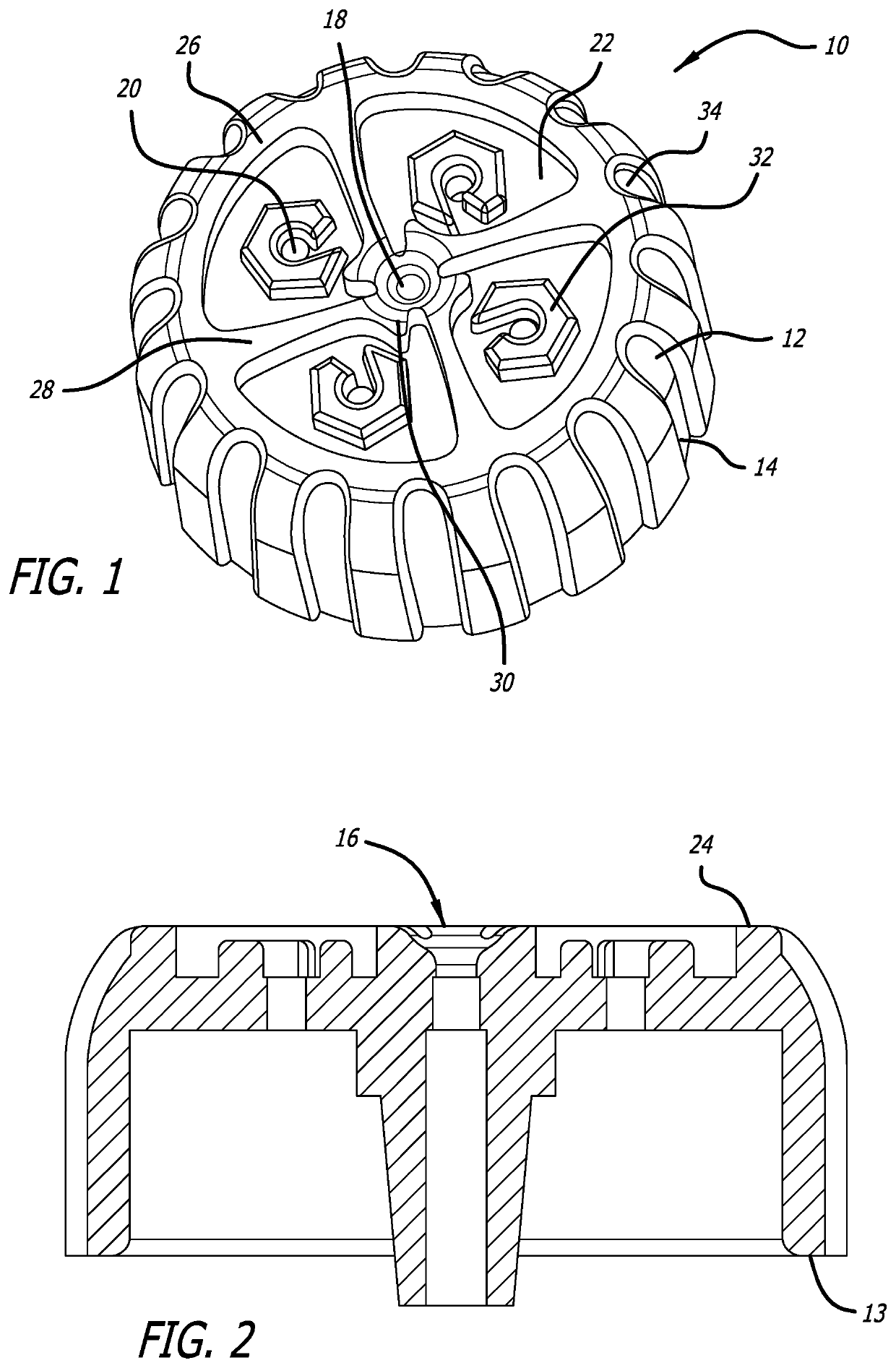
[0012]FIGS. 1 and 2 illustrate a new disposable, removable tip 10 to a microdermabrasion hand piece. The disposable tip is formed in the shape of a cap (like a bottle cap) defining an interior space, and an exterior peripheral wall 12 formed with longitudinal recesses 14 for a more tactile response while applying and removing the tip 10. A central fluid channel 16 in the form of a tubular member is formed in the tip 10 beginning at a proximal end 13 and extending through the interior space to a central orifice 18 at the distal end. The central orifice 18 provides an outlet where fluid pumped through the tip 10 is introduced to an interface between the tip's distal surface and a patient's skin. Four vacuum ports 20 arrayed radially from the central orifice and circumferentially spaced from each other remove the fluid introduced at the central orifice 18. Each vacuum port 20 is located in a recessed sector 22 of the distal surface 24 of the tip 10 that are defined by a circumferential...


PUM


Abstract

The present invention is an applicator tip for a hand piece assembly used in dermal abrasion procedures, the applicator tip having a cap shape with a plurality of apertures that form ports communicating with a fluid supply line in the hand piece assembly and a vacuum source to remove the abrading fluid. The fluid is introduced onto the outer abrading surface of the applicator tip through a first central aperture and spreads out along the outer abrading surface when the applicator tip is placed against the patient's skin. Recesses in the outer abrading surface establish pathways for the abrading fluid to move along as the applicator tip is moved over the patient's skin. The fluid emitting from the central port is moved into one of four quadrants defined by recesses in the outer abrading surface, each quadrant serving as a fluid chamber that receives fluid from the central fluid supply port. Each sector shaped chamber includes within its border a C-shaped barrier with its opening facing a dividing sector wall. As the applicator tip forms a seal with the patient's skin, fluid is introduced through the supply port and through the entrance of the chamber, filling each chamber with working fluid as the working fluid flows to and around the C-shaped barrier. Disposed inside each C-shaped barrier is a respective vacuum port that removes the working fluid from each chamber. Fluid from each chamber is vacuumed through its vacuum port after having flowed around a maze-like path, navigating the C-shaped barrier and sector walls in a vortex flow pattern.

Description

CROSS-REFERENCES TO RELATED APPLICATIONS[0001]This application claims priority to U.S. Provisional Patent Application No. 62 / 957,707, filed Jan. 6, 2020, the content of which is incorporated herein by reference in its entirety.BACKGROUND[0002]The present invention relates to skin treatment tools, and more particularly to a disposable applicator tip to a micro dermabrasion handset that delivers a fluid through a first port and vacuums the fluid through a plurality of peripheral ports.[0003]U.S. Pat. No. 8,048,089 describes a system for treating skin using an apparatus with a removable, disposable tip, the content of which is incorporated herein by reference. Whereas the tip of the U.S. Pat. No. 8,048,089 is spiral, it does not maximize the residency of the fluid on the skin and is less efficient at removing the fluid. Moreover, there is a high ratio of negative surface area to negative pressure with the device of the U.S. Pat. No. 8,048,089. That is, with a single vacuum port the amo...

Claims


Application Information

Patent Timeline
IPC IPC(8): A61B17/54
CPCA61B17/545A61B2017/320004A61B17/54A47K7/04A61B2017/00761A61B2217/005
Inventor NICOLAS, ED F.COHEN, WILLIAM
Owner NICOLAS ED F
Why Eureka
Try Eureka