Metal halide lamp having function for suppressing abnormal discharge
Inactive Publication Date: 2007-06-12
PANASONIC CORP
View PDF16 Cites 4 Cited by
Summary
Abstract
Description
Claims
Application Information
AI Technical Summary
This helps you quickly interpret patents by identifying the three key elements:
Problems solved by technology
Method used
Benefits of technology
Benefits of technology
[0030]According to the stated structure, by suppressing current, abnormal discharge is prevented, and therefore secondary damage caused by abnormal discharge is also prevented.
[0083]According to the stated structure, when the fitting parts are fitted to the narrow tube parts, the narrow tube parts can be easily inserted from the parts that have not been wound. Therefore, workability is improved.
Problems solved by technology
However, while able to start with a low voltage, the following problems exist in conventional metal halide lamps.
As a result, when the metal halide lamp has been used for a substantial length of time, heat fatigue may cause breakage of the arc tube 105, as shown in FIG. 11B.
However, abnormal discharge continues because a portion of the starting wire that is above the melted C part is connected to the electrode 113.
During the progression to this point, breakage of the ballast and the like often occurs due to the large current that accompanies the abnormal discharge.
Furthermore, there is also a possibility of cracking and breakage of the outer tube 102 as a result of the temperature increase caused by the abnormal discharge.
Method used
Image
Click on the blue label to locate the original text in one second.
Reading with bidirectional positioning of images and text.
Examples
first embodiment
[0101]
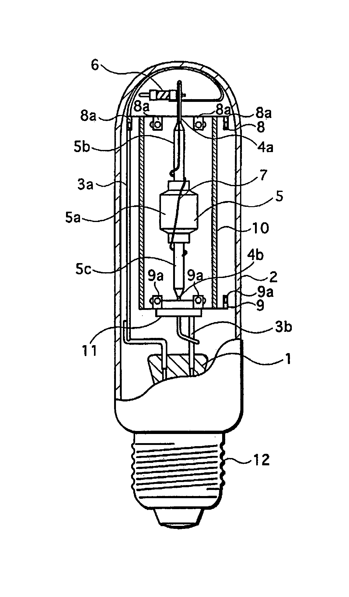
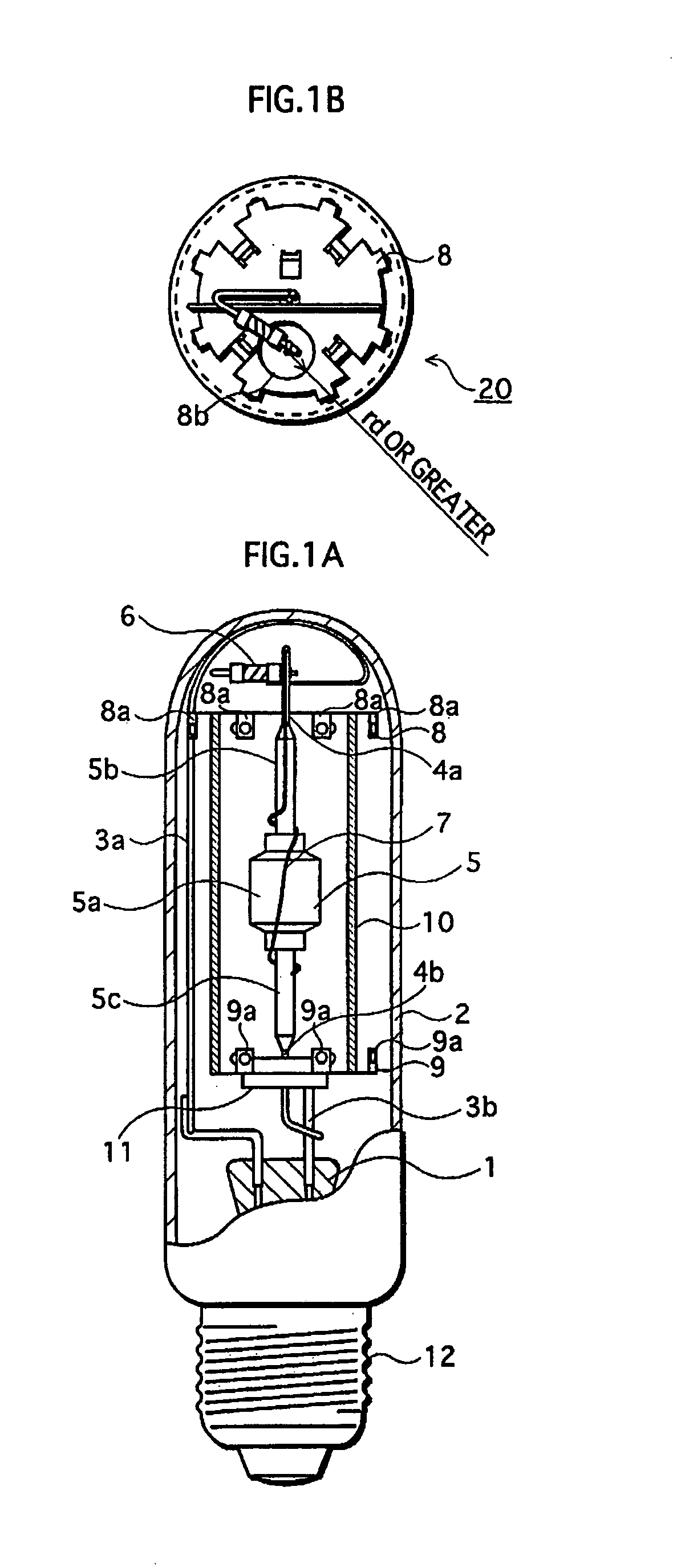
[0102]FIGS. 1A and 1B are schematic diagrams of a metal halide lamp 20 in an embodiment of the present invention.
[0103]The metal halide lamp 20 is a high intensitydischarge lamp that has a power rating of 150 W. As shown in FIG. 1A, the metal halide lamp 20 has a stem 1, an outer tube 2, stem wires 3a and 3b, feeders 4a and 4b, an arc tube 5, a circuit breaking element 6, a starting wire 7, plates 8 and 9, a sleeve 10, insulation 11, and a base 12.
[0104]The stem 1 is a glass member that supports the stem wires 3a and 3b.
[0105]The outer tube 2 is made of hard glass, or the like, and a non-volatile gas such as nitrogen is sealed in the outer tube 2 so as to have a pressure of 100 kPa in operation (approximately 300° C.).
[0106]The base 12 is a bipolar terminal for connecting the metal halide lamp 20 to a lighting socket.
[0107]The stem wire 3a is connected at one end to one of the electrode terminals (not illustrated) in the base 12, and passes through the stem 1 to be welded at...
second embodiment
[0206]Similar to the metal halide lamp of the first embodiment, the metal halide lamp of the second embodiment is a high pressure discharge lamp in which over-current does not flow, even when the main tube part breaks, and secondary damage to the ballast, the outer tube 2, and so on, is prevented.
[0207]FIGS. 8A and 8B are schematic diagrams of a metal halide lamp 21 of the second embodiment of the present invention.
[0208]The metal halide lamp 21 is a high intensity discharge lamp that has a power rating of 150 W. As shown in FIG. 8A, the metal halide lamp 21 has the stem 1, the outer tube 2, the stem wires 3a and 3b, the feeders 4a and 4b, the light emitting tube 5, a circuit breaking element 16, the starter wire 7, the plate 8, the plate 9, the sleeve 10, the insulation 11, and the base 12.
[0209]The majority of these members are the same as those used in the metal halide lamp 20 of the first embodiment. The members that are different in the metal halide lamp 21 of the second embodi...
PUM
Abstract
A metalhalide lamp includes a ceramic arc tube that is composed of a main body and two narrow tube parts provided at respective ends of the main body; a pair of electrodes provided inside the main body; two feeders, each being connected at one end thereof to a different one of the electrodes inside the main body, and extending through a different one of the narrow tube parts, so as to be external to the arc tube at another end; a starting wire that is connected to one of the feeders, and that is in a vicinity of or contacts an outer surface of the arc tube; and a current suppressing unit that is on a current path of the starting wire, and suppresses or cuts off current on the path.
Description
BACKGROUND OF THE INVENTION[0001](1) Field of the Invention[0002]The present invention relates to a technique for safer operation of a metalhalide lamp.[0003](2) Description of the Related Art[0004]A conventional metalhalide lamp, as shown in FIGS. 10A and 10B, has the following structure. An outer tube 102 is sealed at one end, and a base 112 is attached to the other end. The outer tube 102 accommodates an arc tube 105, stem wires 103a and 103b that support the arc tube 105, a glass sleeve 110 that encloses the arc tube 105 and acts to protect against explosions, and plates 108 and 109 that hold respective ends of the sleeve 110.[0005]Nitrogen gas is inserted into the outer tube 102 so as to have a pressure of 100 kPa in operation.[0006]A glass stem 101 is welded at the end of the outer tube 102 that is held by the base 112. The stem 101 supports the two stem wires 103a and 103b that supply current to electrodes.[0007]The arc tube 105 is made up of a cylindrical main tube part th...
Claims
Application Information
Patent Timeline
Application Date:The date an application was filed.
Publication Date:The date a patent or application was officially published.
First Publication Date:The earliest publication date of a patent with the same application number.
Issue Date:Publication date of the patent grant document.
PCT Entry Date:The Entry date of PCT National Phase.
Estimated Expiry Date:The statutory expiry date of a patent right according to the Patent Law, and it is the longest term of protection that the patent right can achieve without the termination of the patent right due to other reasons(Term extension factor has been taken into account ).
Invalid Date:Actual expiry date is based on effective date or publication date of legal transaction data of invalid patent.

